Article Content
Outdoor/Indoor 11kV Cast-Resin Current Transformer LFS-10 – IEC 61869-2 Compliant
Introduction to the LFS-10 Current Transformer
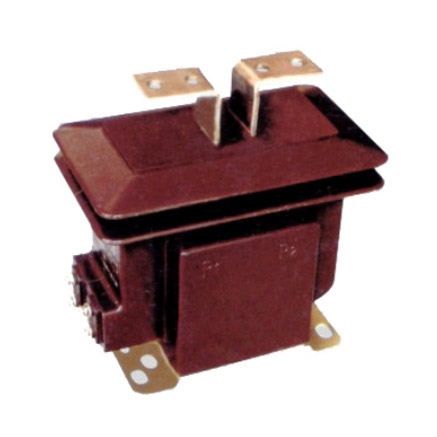
The LFS-10 is a medium-voltage, cast-resin insulated current transformer (CT) engineered for precise current measurement and robust protective relaying in 11kV (IEC-rated) or 10kV (domestic system) electrical networks. Designed for both indoor switchgear and outdoor pole-mounted applications, this instrument transformer leverages advanced vacuum pressure impregnation (VPI) epoxy resin technology to deliver exceptional dielectric strength, environmental resilience, and long-term operational stability. Unlike traditional oil-immersed CTs, the LFS-10 eliminates fire hazards, oil leakage risks, and maintenance-intensive sealing systems, making it ideal for urban substations, industrial facilities, and renewable energy interconnection points where safety and reliability are paramount.
Operating Principle of Cast-Resin Insulation
Cast-resin insulation in the LFS-10 utilizes a high-purity cycloaliphatic epoxy resin system cured under vacuum and pressure to fully encapsulate the primary conductor, secondary windings, and magnetic core. This process eliminates air voids and moisture ingress pathways, achieving a homogeneous dielectric structure with a relative permittivity of approximately 4.2 and volume resistivity exceeding 1×10¹⁴ Ω·cm. The resin matrix provides mechanical support to the windings while maintaining thermal conductivity sufficient for continuous operation at 75°C ambient temperature. Crucially, the absence of liquid insulation eliminates partial discharge risks under normal operating conditions, ensuring compliance with IEC 61869-2’s stringent partial discharge limits (<10 pC at 1.2 × Um/√3).
Advantages Over Oil-Immersed Designs
The LFS-10’s solid insulation offers significant operational advantages over legacy oil-filled CTs. First, it is inherently non-flammable, satisfying IEC 61869-2 Annex C fire performance requirements without additional containment measures. Second, the sealed resin body prevents contamination from dust, salt fog, or industrial pollutants—critical for coastal or heavy-industry environments. Third, thermal cycling does not induce internal pressure changes, eliminating the need for expansion tanks or breathers. Finally, the compact, lightweight design (typically 12–18 kg depending on ratio) simplifies handling and reduces structural support requirements in ring main units (RMUs) or pad-mounted switchgear. These attributes collectively reduce lifecycle costs by minimizing inspection frequency and eliminating oil sampling or replacement procedures.
Typical Applications Overview
The LFS-10 serves dual roles in modern power systems: accurate revenue-grade metering and dependable fault detection for protection schemes. In utility substations, it interfaces with digital multifunction meters (e.g., IEC 61850-compliant IEDs) using 0.2S or 0.5S accuracy classes. Simultaneously, its 5P or 10P protection windings feed overcurrent, earth-fault, or differential relays with linear response up to 20× rated current. Its versatility extends to distributed generation sites (solar farms, biogas plants), where precise export/import metering and anti-islanding protection are mandated by grid codes. The transformer’s IP54 rating ensures reliable performance in both enclosed switchgear compartments and exposed outdoor installations across temperate to tropical climates.
Technical Specifications
The LFS-10 adheres to rigorous dimensional, electrical, and environmental specifications defined by IEC 61869-2 and GB/T 20840.2. Key parameters are summarized below:
| Parameter | Value |
|---|---|
| Rated System Voltage (Um) | 11 kV (IEC) / 10 kV (GB) |
| Rated Primary Current (Ip) | 50 A to 3150 A (standard ratios) |
| Rated Secondary Current (Is) | 1 A or 5 A |
| Accuracy Classes | Metering: 0.2S, 0.5S; Protection: 5P10, 5P20, 10P10, 10P20 |
| Rated Output (Burden) | 5 VA to 30 VA per winding |
| Short-Time Thermal Current | 25 kA for 1 s (at 50 Hz) |
| Rated Insulation Level | Power Frequency Withstand: 28 kV rms, 1 min Lightning Impulse Withstand: 75 kV peak |
| Core Material | Grain-Oriented Electrical Steel (GOES), 0.27 mm thickness |
| Ambient Temperature Range | –25°C to +40°C (extended: –40°C to +55°C optional) |
| Relative Humidity | Up to 95% non-condensing |
| Maximum Altitude | 1000 m above sea level (derating required >1000 m) |
Electrical Performance Characteristics
The LFS-10’s magnetic circuit employs high-permeability GOES laminations with a maximum flux density of 1.7 T at rated current, minimizing core losses (<0.8 W at 1.2× In). For metering windings, composite error at rated current must not exceed ±0.2% (0.2S class) under burdens from 25% to 100% of rated VA. Protection windings maintain ≤10% composite error at specified accuracy limit factors (e.g., 5P20 = 20× In). Phase displacement is limited to ±10 minutes for 0.2S class, critical for vector-based metering in three-phase systems. All windings are fully insulated from the primary conductor and grounded enclosure, with inter-winding insulation tested at 3 kV rms for 1 minute.
Environmental and Mechanical Ratings
Designed for global deployment, the LFS-10 meets IEC 60068-2 environmental test standards. Its UV-stabilized resin housing resists cracking under prolonged solar exposure (tested per IEC 60529 for IP54 ingress protection). Mounting provisions include M12 threaded inserts compatible with standard DIN rails or bracket systems. The creepage distance between primary terminals exceeds 240 mm for 11kV service in pollution degree 3 environments (IEC 60815). Weight varies by ratio: e.g., 50/5 A model ≈12 kg, 2000/1 A ≈18 kg. Terminal blocks accept 16 mm² copper conductors with torque specification of 2.5 N·m.
Typical Applications
The LFS-10’s dual-metering/protection capability enables deployment across diverse infrastructure segments requiring IEC-compliant current sensing at 11kV.
Substation Secondary Metering
In 11kV/0.4kV distribution substations, the LFS-10 provides inputs to revenue meters for billing and SCADA systems for load profiling. A typical configuration uses a 400/5 A ratio with 0.2S accuracy and 10 VA burden, connected to a Class 0.5 kWh meter. The low phase error ensures accurate reactive energy measurement, while the high saturation point (>20× In) prevents waveform distortion during motor starting transients. In smart substations, multiple secondary windings allow simultaneous connection to AMI head-end systems and local HMI panels without signal degradation.
Industrial Power Distribution
Heavy industries (e.g., steel mills, chemical plants) deploy LFS-10 units on 10kV feeders supplying arc furnaces or large compressors. Here, 5P20 protection windings feed instantaneous overcurrent relays set to trip at 8–10× In within 40 ms. The cast-resin body withstands corrosive atmospheres containing SO2 or NH3, unlike oil-filled alternatives prone to gasket degradation. A common ratio is 1200/1 A with 15 VA burden, matching the input impedance of modern numerical relays like SEL-751 or Siemens 7SJ62.
Renewable Energy Integration
Solar photovoltaic (PV) farms use LFS-10 CTs at the 11kV point of interconnection (POI) for both export metering and anti-islanding protection. Grid codes (e.g., IEEE 1547) require accurate measurement down to 10% of rated current—achieved via 0.2S class windings. During cloud-induced irradiance fluctuations, the CT’s linear response prevents false tripping of voltage ride-through functions. Typical installation: 630/1 A ratio, dual secondaries (one for utility meter, one for plant controller), mounted directly on the MV switchgear busbar.
Rural and Suburban Distribution Networks
For overhead line sections in rural electrification projects, pole-mounted LFS-10 units monitor load balancing and detect high-impedance faults. Their compact size allows installation on standard crossarms alongside reclosers. A 200/5 A ratio with 5P10 class provides sufficient sensitivity for earth-fault detection (set at 20% In) while avoiding nuisance trips from capacitive charging currents. The resin housing’s hydrophobic surface sheds rainwater, maintaining insulation integrity during monsoon seasons.
Commercial Building Infrastructure
Large commercial complexes (airports, data centers) employ LFS-10 CTs in 10kV switchrooms feeding step-down transformers. Here, redundancy is achieved via dual-core designs: one core for billing (0.5S), another for building management system (BMS) monitoring (1.0 class). The absence of oil eliminates fire code restrictions in confined spaces, while the low partial discharge ensures electromagnetic compatibility with sensitive IT equipment.
Compliance with International Standards
The LFS-10 is certified to IEC 61869-2:2012 (“Instrument transformers – Part 2: Additional requirements for current transformers”) and aligns with China’s GB/T 20840.2-2014 standard, which adopts IEC 61869-2 with minor national deviations.
IEC 61869-2 Certification Requirements
Full compliance mandates verification of 12 critical parameters: rated insulation level, temperature rise (≤55 K for resin), short-circuit withstand, accuracy under burden variations, and partial discharge magnitude. Type tests include thermal endurance (1000 h at 130°C), impulse voltage distribution, and seismic withstand (if applicable). Routine tests performed on every unit include turns ratio verification (±0.25% tolerance), polarity check, and power frequency withstand at 28 kV for 1 minute. The manufacturer must provide a test report traceable to an ISO/IEC 17025-accredited laboratory.
Alignment with GB/T 20840.2
While GB/T 20840.2 mirrors IEC 61869-2 structurally, key differences exist in labeling and testing emphasis. Chinese standards require explicit marking of “10kV” system voltage (vs. IEC’s 11kV Um), though the insulation level remains identical (28/75 kV). GB/T places greater focus on altitude correction factors—units destined for >1000 m sites must undergo derating calculations per GB/T 11022. Additionally, domestic certification (CCC mark) mandates factory audits by CNAS-accredited bodies, whereas IEC certification relies on third-party type test reports.
Key Differences Between IEC and Domestic Standards
The primary technical divergence lies in accuracy class definitions. IEC 61869-2 defines 0.2S class with strict error limits at 1%, 5%, 20%, 100%, and 120% of rated current, while GB/T 20840.2 historically used broader bands (though recent editions harmonize this). Another distinction is in short-time current ratings: IEC specifies 1-second duration as standard, whereas older GB standards referenced 3-second ratings—now largely obsolete. For international projects, dual-marked LFS-10 units carry both IEC 61869-2 and GB/T 20840.2 compliance labels, facilitating cross-border procurement.
On-Site Testing Procedures
Post-installation verification ensures the LFS-10 performs within IEC 61869-2 tolerances. All tests require de-energized primary circuits and calibrated instruments (accuracy class 0.1 or better).
Insulation Resistance Test
Measure insulation resistance between primary-to-secondary, primary-to-ground, and secondary-to-ground using a 2500 V DC megohmmeter. Acceptance criteria: ≥1000 MΩ at 20°C. Correct for temperature using Rt = R20 × 2(20–t)/10. Values below 500 MΩ indicate moisture ingress or resin cracking—requiring drying or replacement. Perform before and after high-voltage tests to detect insulation damage.
Turns Ratio Test
Apply 1–5 V AC at 50 Hz to the secondary winding and measure induced primary voltage. Calculate actual ratio as Vp/Vs. Compare to nameplate ratio; tolerance must be within ±0.25% for metering classes, ±0.5% for protection. Example: For 400/5 A CT, measured ratio should be 80.0 ±0.2. Use a dedicated turns ratio tester (e.g., Omicron CT Analyzer) for automated validation across all taps.
Polarity Test
Verify reducing polarity per IEC 61869-2 Clause 6.5. Connect a 1.5 V battery between P1 (positive) and P2 (negative). Momentarily close the circuit while monitoring secondary voltage with a DC voltmeter: S1 should show positive deflection when P1 is energized. Incorrect polarity causes 180° phase shift, leading to relay misoperation or metering errors in polyphase systems.
Power Frequency Withstand Voltage Test
Apply 28 kV rms at 50 Hz between primary and grounded secondary/enclosure for 1 minute. Leakage current must remain <1 mA. Gradually ramp voltage (≤1 kV/s) to avoid transient overstress. This test validates insulation integrity after transportation or installation stresses. Do not perform if insulation resistance is <1000 MΩ.
Short-Circuit Test (for CTs)
Unlike VTs, CTs require short-circuit validation of protection windings. Inject 10× rated current into the primary and verify secondary output matches expected value within ±3%. For a 5P10 winding, composite error must be ≤5% at this current level. Use a high-current test set (e.g., Doble F6150) with burden resistor matching the relay input impedance. This confirms correct core sizing and winding integrity.
Preventive Maintenance Guide
Although cast-resin CTs require minimal maintenance, periodic checks extend service life beyond 25 years.
Annual Visual and Electrical Inspection
Inspect for resin cracks, terminal corrosion, or tracking marks on the housing. Clean surfaces with isopropyl alcohol if contaminated. Verify torque on terminal screws (2.5 N·m). Perform insulation resistance and turns ratio tests annually in harsh environments (coastal, industrial), or biennially in controlled indoor settings. Record trends: a 20% drop in insulation resistance over two years warrants investigation.
Five-Year Comprehensive Maintenance
Every 60 months, conduct full IEC 61869-2 routine tests: polarity, ratio, insulation resistance, and partial discharge (if equipment available). Partial discharge should remain <10 pC at 1.2 × (11/√3) kV. Check mounting hardware for loosening due to thermal cycling. Replace any unit showing discoloration (indicating overheating) or physical impact damage.
Maintenance Intervals and Fault Diagnosis
| Interval | Tasks | Fault Indicators |
|---|---|---|
| Annual | Visual inspection, IR test, ratio spot-check | Cracks, carbon tracks, IR <500 MΩ |
| 5 Years | Full electrical tests, PD measurement | Ratio error >0.5%, PD >15 pC |
| After Fault | Post-short-circuit validation | Distorted secondary waveform, overheating |
Common failure modes include secondary winding open-circuit (causing dangerous overvoltage) or core saturation due to incorrect burden. Always ensure secondary circuits are never left open during operation.
Conclusion
The LFS-10 11kV cast-resin current transformer represents a benchmark in medium-voltage instrumentation, combining IEC 61869-2-certified accuracy with the ruggedness required for global deployment. Its VPI epoxy resin encapsulation eliminates the fire and environmental risks associated with oil-filled designs, while the GOES core ensures metrological precision across metering and protection functions. Field-proven in applications ranging from urban substations to remote solar farms, the LFS-10 delivers consistent performance under thermal, electrical, and mechanical stress. With a design life of 25–30 years and minimal maintenance requirements, it offers a compelling total cost of ownership advantage. Compliance with both international (IEC) and domestic (GB) standards facilitates seamless integration into existing 10kV/11kV infrastructure, supporting the transition toward smarter, more resilient power networks. Proper adherence to the outlined testing and maintenance protocols guarantees decades of reliable service, safeguarding both personnel and critical electrical assets.
Frequently Asked Questions (FAQ)
Q1: Can the LFS-10 be used in 10kV systems even though it’s rated 11kV?
A: Yes. The 11kV rating refers to the highest system voltage (Um) per IEC 60038. It is fully compatible with 10kV nominal systems, which have a maximum operating voltage of 11kV.
Q2: What is the maximum allowable burden for a 0.2S class winding?
A: Burden must not exceed the rated VA (e.g., 10 VA) and should stay within 25–100% of that value to maintain 0.2S accuracy. Exceeding burden causes increased ratio and phase errors.
Q3: How often should insulation resistance be tested?
A: Annually in outdoor or polluted environments; every two years in clean indoor switchgear. Always test after any fault event or physical impact.
Q4: Is it safe to leave the secondary winding open-circuited?
A: No. An open secondary can generate lethal voltages (>10 kV) during primary current flow due to core saturation. Always short-circuit unused secondaries with a dedicated link.
Q5: What distinguishes 5P10 from 5P20 protection classes?
A: Both limit composite error to ≤5%, but 5P10 is valid up to 10× rated current, while 5P20 maintains accuracy up to 20× rated current—essential for feeders with high prospective fault levels.
Q6: Can the LFS-10 be installed horizontally?
A: Yes. The cast-resin design is orientation-independent, unlike oil-filled CTs. Ensure adequate clearance to grounded parts per IEC 61439-2.