Article Content
11kV Cast-Resin Current Transformer LJK-100240 for Metering and Protection – IEC 61869-2 Standard
Introduction to the LJK-100240 Current Transformer
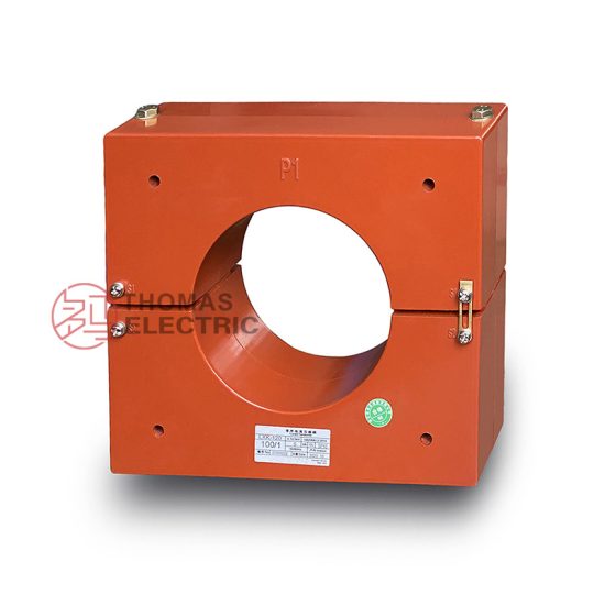
The LJK-100240 is a ring-type, cast-resin insulated current transformer (CT) engineered for high-accuracy measurement and robust protection functions in 11kV medium-voltage networks—equivalent to the domestic 10kV system voltage used in China and select regional grids. Designed in strict accordance with IEC 61869-2 and GB/T 20840.2, this instrument transformer leverages vacuum pressure impregnation (VPI) epoxy resin technology to encapsulate its magnetic core and secondary windings, ensuring superior dielectric strength, mechanical stability, and environmental resilience.
Unlike traditional oil-immersed CTs, which pose fire hazards, require containment systems, and suffer from oil degradation over time, the LJK-100240’s solid insulation eliminates leakage risks and enables maintenance-free operation across diverse climatic conditions. Its compact, dry-type construction supports both indoor and outdoor installations without auxiliary cooling or monitoring infrastructure.
Typical deployment scenarios include utility substations, industrial power distribution centers, renewable energy interconnection points, and commercial complexes where space constraints, safety regulations, and long-term reliability are critical design drivers. The transformer’s toroidal geometry allows for straightforward retrofitting onto existing busbars or cable conductors without system de-energization during installation.
Operating Principle of Cast-Resin Insulation
Cast-resin insulation in the LJK-100240 employs a two-stage VPI process wherein high-purity epoxy resin is vacuum-degassed and then pressure-injected into a mold containing the pre-wound secondary coil and grain-oriented electrical steel (GOES) core. This technique ensures complete void elimination, uniform resin distribution, and optimal adhesion between metallic and polymeric components. The resulting monolithic structure exhibits a dielectric strength exceeding 30 kV/mm, thermal class F (155°C) rating, and resistance to tracking, UV radiation, and partial discharge inception below 10 pC at rated voltage. Crucially, the absence of liquid media prevents moisture ingress and aging-related capacitance drift, preserving metrological integrity over decades of service.
Advantages Over Oil-Immersed Designs
Compared to oil-filled counterparts, the LJK-100240 offers significant operational and safety benefits. It eliminates fire and explosion risks associated with mineral oil, complies with stringent environmental regulations (e.g., RoHS, REACH), and requires no oil sampling, degassing, or level monitoring. Its lightweight design (typically under 15 kg) simplifies handling and reduces structural support requirements. Furthermore, the solid insulation maintains stable dielectric properties across –40°C to +55°C ambient ranges, whereas oil viscosity changes can impair performance in extreme climates. Partial discharge levels remain consistently below 5 pC throughout the transformer’s lifecycle, ensuring compliance with IEC 61869-2’s stringent electromagnetic compatibility criteria.
Typical Applications Overview
The LJK-100240 serves dual roles in metering and protection circuits within 11kV (10kV nominal) systems. In revenue metering applications, its 0.2S or 0.5S accuracy class enables precise energy billing per IEC 62053-22. For protection, it delivers reliable fault current replication up to 20× rated current with 5P10 or 5P20 accuracy classes, ensuring correct relay operation during short circuits. Common installations include ring main units (RMUs), gas-insulated switchgear (GIS) interfaces, solar farm collector substations, and mining facility distribution panels. Its IP54-rated terminal box protects secondary connections from dust and water ingress, supporting reliable telemetry in harsh industrial environments.
Technical Specifications
The LJK-100240 is engineered to meet exacting performance benchmarks under standardized test conditions. Below is a detailed specification table aligned with IEC 61869-2:
| Parameter | Value |
|---|---|
| System Voltage (IEC) | 11 kV |
| Nominal System Voltage (Domestic) | 10 kV |
| Primary Current Rating | 100 A / 200 A / 400 A (selectable via tap) |
| Secondary Current | 1 A or 5 A (standard) |
| Accuracy Class (Metering) | 0.2S, 0.5S |
| Accuracy Class (Protection) | 5P10, 5P20 |
| Rated Burden | 5 VA, 10 VA, 15 VA (per class) |
| Insulation Level (LI/AC) | 75 kV / 28 kV (1 min) |
| Short-Time Thermal Current | 20 kA for 1 s |
| Dynamic Withstand Current | 50 kA peak |
| Core Material | Grain-Oriented Electrical Steel (GOES), CRGO grade |
| Insulation System | VPI Epoxy Resin, Class F (155°C) |
| Ambient Temperature Range | –40°C to +55°C |
| Relative Humidity | Up to 95% non-condensing |
| Altitude Limit | ≤ 1000 m above sea level (derating required above) |
Standard Service Conditions
Per IEC 61869-2 Clause 5, the LJK-100240 is rated for continuous operation under standard service conditions: ambient temperature between –40°C and +55°C, relative humidity not exceeding 95% (non-condensing), and installation altitude not greater than 1000 meters. At altitudes above 1000 m, the dielectric withstand voltage must be derated by 1% per 100 m increment due to reduced air density. The transformer is designed for three-phase systems with balanced loading; however, it tolerates transient unbalances during fault conditions. Continuous exposure to corrosive atmospheres (e.g., coastal salt spray, industrial SO₂) requires optional silicone rubber sheds or hydrophobic coatings—available as factory options.
Electrical Performance Parameters
Key electrical parameters define the LJK-100240’s metrological fidelity. The composite error at rated primary current must not exceed ±0.2% for 0.2S class under burdens up to 10 VA. Phase displacement is limited to ±10 minutes for metering classes. For protection applications, the 5P20 class guarantees that the composite error remains below 5% when subjected to 20 times rated primary current at rated burden. The magnetizing impedance exceeds 20 Ω at 5 A secondary current, minimizing excitation losses. Saturation flux density of the GOES core is maintained below 1.7 T to prevent harmonic distortion during inrush or fault transients. These parameters ensure compatibility with modern digital relays and smart metering infrastructure.
Typical Applications
The LJK-100240’s versatility stems from its dual-certification (IEC and GB), compact form factor, and robust insulation—making it suitable across multiple sectors.
Substation Secondary Metering
In 11kV/0.4kV distribution substations, the LJK-100240 provides high-fidelity current signals to revenue-grade meters compliant with DLMS/COSEM protocols. Installed on outgoing feeders, it enables accurate kWh, kVARh, and demand recording. Its 0.2S accuracy ensures billing precision even at 1% of rated current—a critical requirement for low-load commercial consumers. The transformer’s low phase error (<5 arcmin) supports vector-based power quality analysis, essential for detecting tampering or wiring faults. Integration with SCADA systems via IEC 61850-9-2 LE sampled values is feasible when paired with merging units.
Industrial Power Distribution
Heavy industries such as steel mills, cement plants, and data centers deploy the LJK-100240 on motor control centers (MCCs) and switchgear incomers. Here, its 5P20 protection class reliably triggers circuit breakers during phase-to-phase or ground faults. The 20 kA thermal withstand rating accommodates high prospective fault currents common in industrial networks with low source impedance. The cast-resin body resists vibration from nearby rotating machinery and electromagnetic interference from variable-frequency drives (VFDs), ensuring stable secondary output.
Renewable Energy Integration
Solar photovoltaic (PV) and wind farms utilize the LJK-100240 at collector substation interfaces to monitor generation output and provide anti-islanding protection. Its fast response time (<20 ms) captures transient DC offsets during grid faults, critical for compliance with IEEE 1547 and GB/T 19964 grid codes. The transformer’s immunity to DC saturation—achieved through optimized core cross-section and air-gap minimization—ensures accurate fault detection during asymmetrical short circuits.
Rural and Suburban Distribution Networks
In rural electrification projects, the LJK-100240’s maintenance-free design reduces operational costs over vast geographic areas. Mounted on pole-top transformers or pad-mounted switchgear, it supports remote load profiling and outage detection via AMI (Advanced Metering Infrastructure). Its IP54 terminal enclosure withstands monsoon rains and dust storms prevalent in tropical and arid regions. The 100/200/400 A multi-tap configuration allows field adjustment as load growth occurs, deferring capital expenditure.
Commercial Building Energy Management
Large commercial complexes use the LJK-100240 for tenant submetering and HVAC load monitoring. Its compact diameter (typically ≤120 mm inner bore) fits within tight cable trenches and riser closets. The low self-heating (<10 K rise at 1.2× rated current) prevents thermal stress on adjacent low-voltage cabling. Integration with building management systems (BMS) enables real-time energy dashboards and demand-response automation.
Compliance with International Standards
The LJK-100240 is certified to both global and Chinese national standards, ensuring interoperability and regulatory acceptance across markets.
IEC 61869-2 Compliance Details
IEC 61869-2 governs the performance, testing, and marking of instrument transformers for AC systems. The LJK-100240 meets all mandatory clauses, including:
– **Accuracy verification**: Composite error tested per Annex A using calibrated reference standards traceable to NIST or PTB.
– **Thermal stability**: Verified via 1.2× rated current for 8 hours with temperature rise ≤55 K.
– **Dielectric tests**: Power frequency withstand (28 kV, 1 min) and lightning impulse (75 kV, 1.2/50 µs) applied between primary-ground and secondary-ground.
– **Marking requirements**: Nameplate includes ratio, accuracy class, burden, serial number, and manufacturer ID per Clause 8.
Type tests were conducted at an ISO/IEC 17025-accredited laboratory, with routine tests performed on 100% of production units.
GB/T 20840.2 Alignment
GB/T 20840.2—the Chinese equivalent of IEC 61869-2—imposes additional requirements for domestic deployment. Key alignments include:
– **Short-circuit performance**: Must withstand 25 kA for 1 s (vs. IEC’s 20 kA minimum).
– **Environmental testing**: Salt fog resistance per GB/T 2423.17 for coastal installations.
– **Accuracy at low loads**: 0.2S class must maintain ±0.35% error at 1% rated current (stricter than IEC’s ±0.75%).
All LJK-100240 units shipped to China carry CQC certification and comply with State Grid Corporation’s technical specifications (Q/GDW 13092).
Key Differences Between IEC and Domestic Standards
While IEC 61869-2 focuses on functional performance, GB/T 20840.2 emphasizes grid-specific robustness. Notable differences:
– **Burden definition**: GB uses “VA” while IEC permits “Ω” representation.
– **Test voltages**: GB specifies 32 kV AC withstand for 10kV systems vs. IEC’s 28 kV for 11kV.
– **Core material**: GB mandates CRGO steel with core loss ≤1.0 W/kg at 1.5 T, 50 Hz.
Manufacturers address these via dual-design validation—ensuring one platform satisfies both regimes without performance compromise.
On-Site Testing Procedures
Field commissioning requires rigorous verification to confirm integrity after transport and installation.
Insulation Resistance Test
Perform using a 2500 V DC megohmmeter between primary conductor and grounded flange, and between secondary terminals and ground. Acceptance criterion: ≥1000 MΩ at 20°C. Correct for temperature using RT = R20 × 2(20–T)/10. Low readings indicate moisture ingress or resin cracking—requiring drying or replacement. Test duration: 1 minute after stabilization.
Turns Ratio Test
Apply 1–5 A AC to the primary (via looped conductor) and measure secondary current. Calculate ratio error: [(Ip/Is)meas – N] / N × 100%, where N is nominal ratio (e.g., 100:5 = 20). Tolerance: ±0.2% for 0.2S class, ±1.0% for 5P20. Use a calibrated ratio bridge or portable CT analyzer (e.g., Omicron CT Analyzer). Ensure burden resistor matches rated VA.
Polarity Test
Verify reducing polarity using the DC kick method: connect a 6 V battery momentarily between P1 and P2. Observe secondary voltage spike on a digital multimeter connected to S1–S2. A positive deflection confirms correct polarity (S1 corresponds to P1). Incorrect polarity causes watt-hour meter reversal or directional relay misoperation. Repeat three times for consistency.
Power Frequency Withstand Voltage Test
Apply 28 kV RMS (50 Hz) for 1 minute between primary and ground, and between secondary and ground. Use a calibrated test transformer with overcurrent trip set at 10 mA. No flashover or disruptive discharge permitted. For refurbished units, reduce to 80% (22.4 kV). Always discharge terminals post-test via grounding stick.
Excitation (Saturation) Characteristic Test
Inject increasing AC voltage (0–300 V) into secondary winding while measuring current. Plot V-I curve to identify knee point—defined as 45° inflection per IEC 61869-2 Annex D. For 5P20 class, knee point voltage must exceed 20 × In × Zb (e.g., 20 × 5 A × 2 Ω = 200 V). Low knee voltage indicates core saturation risk during faults.
Preventive Maintenance Guide
Although cast-resin CTs are largely maintenance-free, periodic checks extend service life beyond 30 years.
Annual Visual and Functional Inspection
Inspect for:
– Cracks, tracking, or discoloration on resin surface
– Loose terminal screws or corroded lugs
– Moisture in terminal box (use hygrometer; >70% RH warrants seal replacement)
– Abnormal heating via infrared thermography (>10 K above ambient indicates overload or poor contact)
Verify secondary circuit continuity and grounding integrity. Record insulation resistance annually to establish baseline trends.
Five-Year Comprehensive Maintenance
At five-year intervals, perform:
– Full ratio and polarity re-verification
– Excitation curve comparison against as-new data
– Dielectric absorption test (DAR = R60s/R30s ≥ 1.4)
– Bolt torque check on mounting hardware (typically 25 N·m for M10 studs)
Replace gaskets on terminal box if hardened or cracked. Clean resin surface with isopropyl alcohol to remove conductive dust layers.
Maintenance Intervals and Fault Diagnosis
| Interval | Action | Fault Indicator |
|---|---|---|
| Annually | Visual, IR scan, insulation test | Cracks, hot spots, Rins < 500 MΩ |
| 5 Years | Ratio, excitation, DAR | Knee voltage drop >15%, ratio error drift |
| After Fault | Full suite + dynamic test | Relay misoperation, metering discrepancy |
Common faults include secondary open-circuit (causing core saturation and overvoltage), mechanical damage during installation, and terminal corrosion in humid environments. Never operate with secondary open—always short before disconnecting.
Conclusion
The LJK-100240 11kV cast-resin current transformer represents a benchmark in medium-voltage instrumentation, combining IEC 61869-2 and GB/T 20840.2 compliance with field-proven reliability. Its VPI epoxy resin insulation eliminates the fire, environmental, and maintenance liabilities of oil-filled designs, while the GOES core ensures metrological precision from 1% to 2000% of rated current. Engineered for 25–30 years of continuous service, it delivers consistent performance across utility, industrial, and renewable applications—even under severe thermal, electrical, and climatic stress. The transformer’s dual-role capability (metering and protection) reduces inventory complexity, and its standardized interface simplifies integration with modern digital substations. With rigorous on-site testing and a disciplined preventive maintenance regimen, operators can achieve near-zero lifecycle failure rates, ensuring grid safety, revenue accuracy, and regulatory compliance for decades. As power systems evolve toward smarter, more distributed architectures, the LJK-100240’s robust design and certification pedigree position it as a cornerstone component in next-generation 11kV infrastructure.
Frequently Asked Questions (FAQ)
Q1: Can the LJK-100240 be used on a 10kV system even though it’s rated 11kV?
Yes. The 11kV IEC rating corresponds to the maximum system voltage (Um = 12 kV), making it fully compatible with 10kV nominal systems (Un = 10 kV, Um = 11.5 kV per GB standards). No derating is required.
Q2: What is the acceptable tolerance for turns ratio error during field testing?
For 0.2S class: ±0.2%; for 0.5S: ±0.5%; for 5P10/5P20: ±1.0%. Measurements must be taken at rated burden using calibrated equipment traceable to national standards.
Q3: Is it safe to leave the secondary terminals open during maintenance?
No. An open secondary circuit during primary energization induces dangerous overvoltages (>10 kV) due to core saturation. Always short S1–S2 with a dedicated link before disconnecting loads.
Q4: How often should insulation resistance be measured?
Annually as part of preventive maintenance. A sudden drop below 500 MΩ warrants immediate investigation for moisture ingress or insulation degradation.
Q5: Does the LJK-100240 require special tools for installation?
No. Its ring-type design slips over busbars or cables without disassembly. Torque wrenches (set to 25 N·m) are recommended for terminal bolts to prevent under/over-tightening.
Q6: Can multiple accuracy classes be provided in one unit?
Yes. Dual-core variants offer separate windings for metering (0.2S) and protection (5P20), each with independent terminals and burdens—ideal for integrated substation applications.