Article Content
Outdoor/Indoor 11kV Cast-Resin Current Transformer LZX-10 – IEC 61869-2 Compliant
Introduction to the LZX-10 Current Transformer
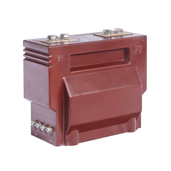
The LZX-10 is a precision-engineered, cast-resin insulated current transformer (CT) rated for 11kV systems per IEC standards, with domestic compatibility at 10kV nominal voltage. Designed for both indoor switchgear and outdoor substation applications, this instrument transformer provides accurate current scaling for metering, protective relaying, and control functions in medium-voltage distribution networks. Its construction leverages vacuum pressure impregnation (VPI) epoxy resin technology to encapsulate high-permeability grain-oriented electrical steel (GOES) cores, ensuring long-term dielectric integrity and mechanical robustness under thermal and environmental stress.
Operating Principle of Cast-Resin Insulation
Cast-resin insulation in the LZX-10 employs a thermosetting epoxy compound that fully encapsulates the primary conductor, secondary windings, and magnetic core under vacuum conditions. This process eliminates air voids and moisture ingress pathways, critical for maintaining consistent partial discharge performance below 10 pC at 1.2 × Um/√3 (where Um = 12 kV). The resin matrix exhibits a Comparative Tracking Index (CTI) ≥ 600, providing excellent resistance to surface tracking in polluted environments. Unlike oil-filled alternatives, the solid insulation system requires no maintenance, contains no flammable materials, and complies with IEC 61869-2 requirements for fire behavior (non-dripping, self-extinguishing per IEC 60695).
Advantages Over Oil-Immersed Designs
Compared to traditional oil-immersed CTs, the LZX-10’s cast-resin design eliminates risks associated with oil leakage, degradation, and fire hazards—particularly vital in confined indoor switchrooms or environmentally sensitive zones. The absence of liquid insulation also removes the need for periodic oil sampling, gas analysis, or conservator tank inspections. Thermally, the epoxy resin offers superior heat dissipation due to its high thermal conductivity (~0.8 W/m·K), enabling stable operation at ambient temperatures from –40°C to +40°C. Additionally, the monolithic structure resists mechanical vibration and seismic loads up to 0.5g, making it suitable for industrial facilities with heavy machinery or regions prone to moderate seismic activity.
Typical Application Overview
The LZX-10 is deployed across utility substations, industrial plants, renewable energy interconnection points, and commercial complexes where reliable current transformation is essential. It interfaces directly with revenue-class kWh meters (Class 0.2S/0.5S), digital protective relays (e.g., overcurrent, differential, earth-fault), and SCADA systems. With dual-core configurations available (e.g., one core for metering, another for protection), the LZX-10 supports simultaneous compliance with accuracy and saturation requirements—ensuring metering fidelity during normal load while delivering sufficient knee-point voltage for relay coordination during fault conditions.
Technical Specifications
The LZX-10 adheres to stringent electrical and environmental parameters defined by IEC 61869-2 and GB/T 20840.2, ensuring global interoperability and performance consistency.
| Parameter | Value |
|---|---|
| Rated System Voltage (Ur) | 11 kV (IEC), 10 kV (domestic) |
| Maximum System Voltage (Um) | 12 kV |
| Primary Current Ratings | 50 A to 3150 A (standard); custom up to 4000 A |
| Secondary Current | 1 A or 5 A (per IEC 61869-2) |
| Accuracy Classes | Metering: 0.2S, 0.5S; Protection: 5P10, 5P20, 10P10 |
| Rated Output (Burden) | 5 VA, 10 VA, 15 VA, 30 VA (at rated current) |
| Insulation Level (LI/AC) | 75 kV / 28 kV (1 min power frequency withstand) |
| Partial Discharge | <10 pC at 1.2 × Um/√3 |
| Creepage Distance | ≥25 mm/kV (medium pollution); ≥31 mm/kV (heavy pollution) |
| Ambient Temperature Range | –40°C to +40°C |
| Altitude Limit | ≤1000 m (derating required above 1000 m) |
| Relative Humidity | Up to 95% non-condensing |
Electrical Performance Parameters
The LZX-10’s accuracy is validated under IEC 61869-2 test protocols. For metering class 0.2S, composite error must not exceed ±0.2% at 20% to 120% of rated primary current, with phase displacement ≤±10 minutes. Protection cores (e.g., 5P20) guarantee ≤5% composite error at 20× rated current, provided burden does not exceed rated VA. The knee-point voltage (Vk) for 5P20 cores typically exceeds 300 V, ensuring adequate saturation margin during high-magnitude faults. Secondary winding resistance is tightly controlled (±5% tolerance) to maintain burden compatibility with connected devices.
Environmental and Mechanical Ratings
Designed for both indoor metal-enclosed switchgear (IP2X) and outdoor pole-mounted installations (IP54 equivalent via housing), the LZX-10 withstands UV exposure, salt fog (per IEC 60068-2-52), and thermal cycling without cracking or delamination. The creepage distance is engineered per pollution degree: 300 mm minimum for 11kV in medium-pollution zones (e.g., urban substations), extendable to 372 mm for coastal or industrial areas. Mounting options include flange (M12 bolts) or bracket support, with weight ranging from 8 kg (50/5A) to 18 kg (3150/1A).
Typical Applications
The LZX-10 serves as a foundational component in diverse power infrastructure scenarios requiring precise, reliable current transformation.
Substation Secondary Metering
In 11kV/0.4kV distribution substations, the LZX-10 feeds Class 0.2S secondary currents to revenue meters for billing accuracy. Its low phase error ensures minimal reactive energy distortion, critical for power factor correction systems. For example, a 400/5A LZX-10 with 15 VA output drives a three-phase smart meter over 20-meter copper leads (2.5 mm²), staying within 5 VA effective burden. The cast-resin body prevents condensation-induced errors common in humid climates, unlike open-frame designs.
Industrial Power Distribution
Within manufacturing plants, the LZX-10 monitors feeders supplying motors, transformers, and rectifiers. A dual-core variant (e.g., 600/1A: 0.5S/15VA + 5P10/30VA) simultaneously supports energy management and motor protection relays. During arc-flash events, the high short-time thermal withstand (e.g., 25 kA for 1 s) prevents internal damage, maintaining post-fault diagnostic capability. Its compact footprint fits retrofit into legacy switchgear without busbar modification.
Renewable Energy Integration
At solar PV or wind farm collection points, the LZX-10 interfaces with anti-islanding and over/under-frequency relays. Bidirectional current flow (from grid export to import) is handled without accuracy drift due to symmetrical core magnetization. In a 10 MW solar plant, 1250/5A units with 5P20 cores ensure rapid tripping during DC injection faults, while 0.5S cores log export energy for feed-in tariff compliance.
Rural and Suburban Distribution Networks
For overhead line monitoring in remote areas, the LZX-10’s outdoor-rated housing resists dust, rain, and temperature swings. Mounted on pole-top reclosers, it enables automated sectionalizing based on fault current magnitude. A 200/5A unit with 10P10 rating triggers recloser lockout after three faults, minimizing outage duration. Its 25-year service life reduces replacement logistics in hard-to-access locations.
Compliance with International Standards
The LZX-10 is certified to IEC 61869-2 (Instrument transformers – Part 2: Additional requirements for current transformers) and aligns with China’s GB/T 20840.2, ensuring global acceptance.
IEC 61869-2 Certification Requirements
IEC 61869-2 mandates rigorous type, routine, and sample tests. Type tests include temperature rise (≤60 K for resin), impulse withstand (75 kV BIL), and accuracy verification across burden ranges. The LZX-10 undergoes full-wave lightning impulse testing per IEC 60060-1, with waveform tolerance ±3% peak and ±20% time-to-half-value. Accuracy validation uses calibrated reference CTs traceable to national standards, with uncertainty ≤0.05%. Each unit receives a test report detailing ratio error, phase displacement, and excitation curve.
Alignment with GB/T 20840.2
GB/T 20840.2 mirrors IEC 61869-2 but includes localized requirements: higher creepage (≥31 mm/kV for Class IV pollution), mandatory short-time current withstand of 25 kA/1s (vs. IEC’s 20 kA/1s for some ratings), and stricter partial discharge limits (<5 pC at factory test). The LZX-10 meets both by design—its resin formulation passes GB-specific flame retardancy (oxygen index ≥32%) and thermal shock tests (–40°C to +80°C cycling).
Key Differences Between IEC and Domestic Standards
While IEC emphasizes harmonized global performance, GB standards prioritize harsh environmental resilience common in China’s industrial corridors. For instance, GB/T 20840.2 requires salt fog testing for 1000 hours (vs. IEC’s optional 500 hours), and mandates core remanence checks after demagnetization. The LZX-10’s GOES core achieves remanence ≤10% of saturation flux density, satisfying both regimes. Certification bodies like TÜV (for IEC) and CQC (for GB) issue separate conformity marks, both affixed to the nameplate.
On-Site Testing Procedures
Post-installation verification ensures the LZX-10 performs per specifications. All tests follow IEC 61869-2 Annex D and IEEE C57.13 guidelines.
Insulation Resistance Test
Using a 2500 V DC megohmmeter, measure insulation resistance between primary-secondary, primary-ground, and secondary-ground. Acceptance criterion: ≥1000 MΩ at 20°C. Correct for temperature using Rt = R20 × 2(20–t)/10. Values below 500 MΩ indicate moisture ingress or resin cracking, requiring drying or replacement. Perform before and after power frequency withstand tests.
Turns Ratio Test
Apply 1–5 A AC to the primary (using a variable ratio test set) and measure secondary current. Calculate actual ratio = Ip/Is. Tolerance per IEC 61869-2: ±0.25% for metering classes, ±1% for protection. For a 800/5A unit, measured secondary at 4 A primary should be 0.025 A ±0.0000625 A. Deviations >2% suggest winding shorts or incorrect tap selection.
Polarity Test
Verify reducing polarity (IEC standard) using a DC source and galvanometer. Momentarily connect (+) to P1 and (–) to P2; secondary terminal S1 should show positive kick. Incorrect polarity causes relay misoperation—e.g., differential schemes may trip on through-faults. Digital testers automate this via phase-angle comparison; acceptable deviation: ≤±2°.
Power Frequency Withstand Voltage Test
Apply 28 kV RMS (50 Hz) for 1 minute between primary-ground and secondary-ground. Monitor for flashover, excessive leakage current (>1 mA), or audible discharge. Use a calibrated HV transformer with overcurrent trip (≤5 A). Conduct only after insulation resistance confirms dryness. Failure indicates voids or contamination in resin.
Short-Circuit Test (for CTs)
Unlike VTs, CTs require short-circuit validation. Inject 10× rated current (e.g., 8000 A for 800/5A) for 1 second. Verify no mechanical deformation, winding displacement, or insulation damage. Post-test, recheck ratio and insulation resistance. This confirms thermal and electrodynamic withstand capability per IEC 61869-2 Clause 12.
Preventive Maintenance Guide
Although cast-resin CTs are largely maintenance-free, periodic checks extend service life and prevent unexpected failures.
Annual Visual and Electrical Inspection
Inspect for surface cracks, tracking marks, or discoloration (indicating overheating). Clean housing with dry cloth—never solvents. Measure insulation resistance annually; a 20% drop from baseline warrants investigation. Check terminal tightness (torque: 12 N·m for M8 studs) to prevent hot spots. In coastal areas, verify creepage path integrity against salt deposits.
Five-Year Comprehensive Maintenance
Every 60 months, perform full electrical tests: ratio, polarity, excitation curve, and burden verification. Plot excitation curve (Vs vs. Is) and compare to factory data; a 15% increase in knee-point voltage suggests core degradation. Demagnetize if remanence affects accuracy (apply decaying AC at 120% rated burden). Replace if partial discharge exceeds 20 pC during on-site PD testing.
Maintenance Intervals and Fault Diagnosis
| Interval | Action | Fault Indicator |
|---|---|---|
| Annually | Visual check, IR test | Cracks, IR <500 MΩ |
| Every 3 years | Ratio & polarity verification | Error >1%, wrong polarity |
| Every 5 years | Excitation curve, demagnetization | Vk shift >15% |
| After fault | Full electrical suite | Mechanical damage, ratio shift |
Common faults include open secondary circuits (causing dangerous overvoltage), core saturation from excessive burden, and terminal corrosion. Always short secondary terminals before disconnecting meters.
Conclusion
The LZX-10 11kV cast-resin current transformer represents a benchmark in reliability, accuracy, and compliance for modern power systems. By integrating GOES magnetic cores with void-free VPI epoxy resin insulation, it delivers exceptional performance across metering (Class 0.2S) and protection (5P20) applications while eliminating the fire, leakage, and maintenance risks inherent in oil-filled alternatives. Certified to both IEC 61869-2 and GB/T 20840.2, the LZX-10 ensures seamless integration into global utility and industrial networks—from urban substations to remote renewable sites. Its robust environmental rating (–40°C to +40°C, IP54-equivalent) and 25–30 year design life minimize lifecycle costs, while standardized testing protocols guarantee consistent field performance. With precise adherence to international standards and proven resilience under electrical, thermal, and mechanical stress, the LZX-10 remains a trusted solution for critical current measurement and protection tasks in 10kV/11kV infrastructure worldwide.
Frequently Asked Questions (FAQ)
Q1: Can the LZX-10 be used in 10kV domestic systems even though it’s rated 11kV?
A: Yes. The 11kV rating per IEC corresponds to a 12 kV maximum system voltage (Um), which safely covers 10kV domestic systems (Um = 11.5 kV per GB standards). No derating is required.
Q2: What is the maximum allowable burden for a 5P20 protection core?
A: The burden must not exceed the rated VA (e.g., 30 VA) specified on the nameplate. Exceeding this reduces the knee-point voltage, risking core saturation during faults and relay miscoordination.
Q3: How often should the insulation resistance test be performed?
A: Annually as part of preventive maintenance, and always after any suspected insulation stress (e.g., nearby lightning strike, flooding, or thermal overload).
Q4: Is demagnetization necessary after every fault?
A: Only if post-fault ratio tests show errors exceeding tolerance. High-magnitude faults can leave residual magnetism; demagnetize using a decaying AC current at 120% of rated burden.
Q5: Can the LZX-10 be installed horizontally?
A: Yes. The cast-resin design is orientation-independent. Ensure proper creepage clearance to grounded parts per local codes (minimum 125 mm for 11kV).
Q6: What happens if the secondary circuit is left open?
A: Dangerous overvoltages (several kV) can develop, risking insulation failure and personnel hazard. Always short secondary terminals with a dedicated link before disconnecting loads.