Article Content
Introduction to the SZW-10 Current Transformer
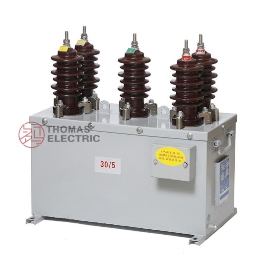
The SZW-10 is a high-reliability, cast-resin insulated current transformer (CT) engineered for operation in 11kV (IEC-rated) or 10kV (domestic system equivalent) medium-voltage networks. Designed in strict accordance with IEC 61869-2 and GB/T 20840.2, this device serves critical roles in both metering and protective relaying applications across utility substations, industrial facilities, and renewable energy interconnection points. Its robust construction leverages modern insulation and magnetic materials to ensure long-term performance under demanding environmental and electrical conditions.
Operating Principle of Cast-Resin Insulation
Cast-resin insulation in the SZW-10 employs vacuum pressure impregnation (VPI) of cycloaliphatic epoxy resin around the primary conductor, secondary windings, and magnetic core assembly. This process eliminates air voids and moisture ingress pathways, resulting in superior dielectric strength and partial discharge resistance (<5 pC at 1.2 × Um/√3). Unlike oil-filled alternatives, the solid dielectric provides inherent fire safety (non-flammable), minimal maintenance, and immunity to oil leakage or degradation over time. The resin matrix also offers excellent mechanical rigidity, protecting internal components from vibration and thermal cycling stresses encountered in outdoor installations.
Advantages Over Oil-Immersed Designs
Compared to traditional oil-immersed CTs, the SZW-10’s cast-resin design eliminates fire hazards, reduces environmental compliance burdens, and simplifies handling during transport and installation. It requires no oil sampling, level monitoring, or breather maintenance. Furthermore, its compact footprint enables easier integration into space-constrained switchgear bays. The absence of liquid insulation also ensures consistent dielectric performance across wide temperature ranges (–40°C to +40°C ambient), without viscosity-related response delays during fault transients. These attributes make it particularly suitable for urban substations, indoor switchrooms, and locations with stringent fire codes.
Typical Applications Overview
The SZW-10 is commonly deployed in 11kV ring main units (RMUs), pad-mounted transformers, and overhead line sectionalizing points. It supports revenue-grade metering (accuracy class 0.2S or 0.5S) and high-speed protection schemes (e.g., 5P10 or 5P20 classes). Its dual-secondary configuration allows simultaneous connection to metering and protection circuits without cross-interference. In distributed generation sites—such as solar farms or biogas plants—the SZW-10 enables accurate export/import measurement and anti-islanding protection coordination. Its reliability under continuous thermal loading (up to 1.2 × rated current) ensures stable operation in heavily loaded distribution feeders.
Technical Specifications
The SZW-10 is engineered to meet precise electrical and environmental parameters defined by international and domestic standards. Below is a comprehensive specification table followed by contextual details on service conditions and performance envelopes.
| Parameter | Value |
|---|---|
| Rated Voltage (Um) | 12 kV (system voltage 11 kV IEC / 10 kV domestic) |
| Primary Current Ratings | 50 A to 3000 A (standard); custom ratios available |
| Secondary Current | 1 A or 5 A (per IEC 61869-2) |
| Accuracy Classes | Metering: 0.2S, 0.5S; Protection: 5P10, 5P20 |
| Rated Output (Burden) | 5 VA, 10 VA, 15 VA, 30 VA (at rated accuracy) |
| Insulation Level (LI/AC) | 75 kV lightning impulse / 28 kV power frequency withstand (1 min) |
| Short-Time Thermal Current | 25 kA for 1 s (I²t = 625 kA²s) |
| Dynamic Withstand Current | 63 kA peak |
| Core Material | Grain-Oriented Electrical Steel (GOES), low-loss grade |
| Insulation System | VPI cycloaliphatic epoxy resin, UL 94 V-0 rated |
| Ambient Temperature Range | –40°C to +40°C |
| Altitude Limit | ≤ 1000 m above sea level (derating required above) |
| Relative Humidity | Up to 95% non-condensing |
| Expected Service Life | 25–30 years under normal operating conditions |
Standard Service Conditions
The SZW-10 is rated for standard service conditions per IEC 61869-2: ambient temperature between –40°C and +40°C, relative humidity up to 95% (non-condensing), and installation altitude not exceeding 1000 meters. At higher altitudes (e.g., 2000 m), the external insulation clearance must be increased by approximately 12%, though internal resin insulation remains unaffected. The transformer is designed for continuous operation at 1.2 × rated primary current without exceeding temperature rise limits (≤ 60 K for windings). It is suitable for both indoor and outdoor mounting, with UV-stabilized resin housing for prolonged sun exposure resistance.
Electrical Performance Envelope
Under nominal load, the SZW-10 maintains ratio error within ±0.2% (for 0.2S class) and phase displacement below ±10 minutes at 100% rated current. For protection applications, the 5P20 class guarantees composite error ≤5% at 20 × rated current with specified burden. The GOES core minimizes hysteresis and eddy current losses, ensuring stable excitation characteristics even during DC offset fault currents. Saturation flux density is maintained above 1.7 T, preventing premature saturation during high-magnitude transients. The secondary terminals are rated for 10 A continuous and feature IP2X finger-safe enclosures to prevent accidental contact.
Typical Applications
The SZW-10 cast-resin current transformer is widely deployed across diverse power infrastructure segments due to its dual functionality in metering and protection, combined with environmental resilience.
Substation Secondary Metering
In 11kV/10kV distribution substations, the SZW-10 provides accurate current signals to revenue meters and SCADA systems. When configured with 0.2S or 0.5S accuracy class and connected to a 5 VA or 10 VA burden, it meets IEC 62053-22 requirements for billing-grade measurement. Its low phase error ensures correct power factor calculation, critical for reactive energy billing. In smart grid deployments, the CT interfaces with digital meters via analog inputs or, when paired with merging units, supports IEC 61850-9-2 LE sampled values. The cast-resin body resists tracking from pollution, making it ideal for coastal or industrial zones with high salt or chemical aerosol concentrations.
Industrial Power Distribution
Within manufacturing plants and data centers, the SZW-10 monitors feeder loads and enables selective coordination of circuit breakers. Its 5P10 or 5P20 protection class ensures reliable tripping during bolted faults while avoiding nuisance operations during motor inrush (typically 6–8 × rated current for 0.2 s). The transformer’s high short-circuit withstand capability (25 kA/1s) aligns with typical industrial bus fault levels. Installation inside metal-enclosed switchgear benefits from the CT’s compact dimensions and lack of flammable materials, satisfying NFPA 70E and local fire safety codes.
Renewable Energy Integration
At solar photovoltaic (PV) or wind farm interconnection points, the SZW-10 supports both export metering and anti-islanding protection. During grid faults, its linear response up to 20 × rated current allows protective relays to detect loss-of-mains conditions accurately. The dual-secondary design permits one winding for utility metering and another for plant-level energy management systems. The CT’s immunity to electromagnetic interference (EMI) from inverters ensures signal integrity, while its wide temperature tolerance accommodates desert or alpine site conditions.
Rural and Suburban Distribution Networks
In overhead line applications, pole-mounted SZW-10 units feed recloser controls and remote terminal units (RTUs). Their maintenance-free nature reduces operational costs in geographically dispersed networks. The 1 A secondary option minimizes copper losses over long cable runs to control houses. With a creepage distance of ≥25 mm/kV (medium pollution severity), the housing resists flashover during fog or light rain. Utilities often specify the SZW-10 for automated sectionalizing schemes due to its proven reliability over decades of field service.
Compliance with International Standards
The SZW-10 is certified to IEC 61869-2:2012 (“Instrument transformers – Part 2: Additional requirements for current transformers”) and fully aligned with China’s GB/T 20840.2-2014 standard, which adopts IEC 61869-2 with minor national deviations.
IEC 61869-2 Compliance Details
IEC 61869-2 defines performance, testing, and marking requirements for instrument transformers. The SZW-10 complies with all mandatory clauses, including:
– Type tests: temperature rise, short-circuit withstand, impulse voltage, and accuracy verification.
– Routine tests: power frequency withstand (28 kV, 1 min), partial discharge (<5 pC at 1.2 × Um/√3), and turns ratio/polarity checks.
- Accuracy verification per Annex B, using standardized test circuits with calibrated reference CTs.
Markings include rated voltage, ratio, accuracy class, burden, and standard reference (e.g., “IEC 61869-2”). The transformer undergoes third-party type testing at accredited laboratories (e.g., KEMA, CESI) with certification valid for five years.
GB/T 20840.2 Alignment and Differences
GB/T 20840.2 mirrors IEC 61869-2 but includes supplementary requirements for Chinese grid operators:
– Mandatory seismic withstand testing (0.3g horizontal acceleration).
– Stricter partial discharge limits (<3 pC) for transformers used in urban substations.
- Requirement for dual-language (Chinese/English) nameplates.
Despite these additions, the core electrical specifications remain harmonized. The SZW-10 carries both CQC (China Quality Certification) and IEC CB Scheme marks, facilitating global deployment. Notably, GB/T uses 10kV as the nominal system voltage, whereas IEC specifies 11kV; the SZW-10’s 12 kV Um rating satisfies both frameworks.
Testing and Certification Requirements
Full compliance requires successful completion of:
– **Type Tests**: Conducted once per design, including thermal stability, dynamic short-circuit, and accuracy under varying burdens.
– **Routine Tests**: Performed on every unit—insulation resistance (>1000 MΩ at 2500 V DC), ratio error (±0.1% tolerance for metering class), and polarity (reducing polarity confirmed via DC kick test).
– **Special Tests** (optional): Seismic, chopped wave impulse, or elevated temperature aging.
Certification documentation includes test reports, material declarations (RoHS, REACH), and a Declaration of Conformity signed by the manufacturer’s quality manager.
On-Site Testing Procedures
Post-installation and periodic field testing ensures the SZW-10 operates within design tolerances. All procedures follow IEC 61869-2 Annex D and IEEE C57.13 guidelines.
Insulation Resistance Test
Using a 2500 V DC megohmmeter, measure insulation resistance between primary-to-ground, secondary-to-ground, and primary-to-secondary. Acceptance criteria: >1000 MΩ at 20°C. Correct for temperature using R₂₀ = Rₜ × 2^((20–t)/10). Low readings (<100 MΩ) indicate moisture ingress or resin cracking. Perform before and after cleaning contaminated surfaces. Ensure all secondary terminals are shorted and grounded during primary-side testing to avoid damaging connected meters.
Turns Ratio Test
Apply a low-voltage AC source (5–50 V) to the primary and measure secondary voltage. Calculate actual ratio = V_primary / V_secondary. Compare to nameplate ratio; tolerance is ±0.1% for 0.2S class and ±0.5% for 5P20. Use a dedicated ratio tester (e.g., Omicron CT Analyzer) for automated comparison against reference values. Deviations beyond tolerance suggest winding shorts or incorrect tap selection. Always demagnetize the core before ratio testing to eliminate remanence effects.
Polarity Test
Verify reducing polarity using the DC kick method: connect a 6–12 V battery momentarily between P1 (+) and P2 (–). Observe a momentary positive deflection on a DC milliammeter connected to S1 (+) and S2 (–). Reversed deflection indicates incorrect polarity, which would cause metering errors or relay misoperation. Alternatively, use an AC phase comparator—secondary voltage should lag primary by 180°. Polarity errors are critical in differential protection schemes and must be corrected before energization.
Power Frequency Withstand Voltage Test
Apply 28 kV RMS at 50 Hz between primary and ground (with secondary shorted and grounded) for 1 minute. The test verifies insulation integrity after transport or installation stress. Use a calibrated HV test set with overcurrent trip (≤100 mA). Partial discharge activity during the test should remain <10 pC. If breakdown occurs, inspect for surface contamination or mechanical damage. This test is typically performed only during commissioning or after major maintenance—not annually.
Excitation (Saturation) Characteristic Test
For CTs, the open-circuit test is replaced by excitation curve measurement. Gradually increase AC voltage on the secondary (primary open) while recording current. Plot volts vs. amps to identify knee-point voltage (Vk). For 5P20 class, Vk must exceed 20 × (rated secondary voltage + I_sec × burden). A depressed knee-point indicates core saturation risk during faults. Compare curves to factory baseline; significant deviation suggests core damage or shorted turns. Demagnetize after testing to restore linear performance.
Preventive Maintenance Guide
Proactive maintenance extends the SZW-10’s service life and prevents unexpected failures. The cast-resin design minimizes routine tasks but does not eliminate inspection needs.
Periodic Visual and Functional Inspection
Conduct annual inspections including:
– **Visual Check**: Cracks, discoloration, tracking marks, or resin chalking on the housing.
– **Terminal Integrity**: Tightness of primary busbar clamps and secondary screw terminals (torque: 2.5 N·m for M6).
– **Grounding Continuity**: Measure resistance from grounding lug to substation grid (<0.1 Ω).
- **Secondary Circuit Verification**: Confirm no open circuits (which could cause dangerous overvoltages).
Clean surfaces with isopropyl alcohol if contaminated with dust or salt. Replace damaged terminal covers immediately. Document findings in asset management systems for trend analysis.
Maintenance Intervals and Fault Diagnosis
Follow this schedule:
– **Annual**: Visual inspection, insulation resistance, and secondary loop continuity.
– **5-Year**: Full electrical tests (ratio, polarity, excitation curve).
– **After Fault Events**: Immediate post-fault inspection and excitation test to detect core damage.
Common faults include:
– **Ratio Drift**: Caused by partial winding shorts; diagnosed via excitation curve shift.
– **Insulation Degradation**: Indicated by low IR or high PD; often due to UV exposure or thermal cycling.
– **Terminal Corrosion**: Leads to heating; mitigated by using tin-plated or silver-plated contacts.
Replace the unit if knee-point voltage drops below 80% of original value or if cracks penetrate the resin wall.
Conclusion
The SZW-10 11kV cast-resin current transformer represents a mature, standards-compliant solution for modern medium-voltage networks. Its integration of GOES silicon steel cores and VPI epoxy resin insulation delivers exceptional accuracy, thermal stability, and dielectric reliability across both metering and protection functions. Compliance with IEC 61869-2 and GB/T 20840.2 ensures interoperability in global markets, while the maintenance-free design reduces lifecycle costs compared to oil-filled alternatives. Field-proven in environments ranging from arid deserts to humid coastal regions, the SZW-10 maintains performance integrity under continuous loading and severe fault conditions. With a design life of 25–30 years and robust resistance to pollution, UV radiation, and thermal stress, it provides utilities and industrial operators with a dependable foundation for revenue assurance, system protection, and grid modernization initiatives. Proper adherence to the outlined testing and maintenance protocols further enhances operational safety and longevity, making the SZW-10 a technically sound choice for critical 11kV/10kV infrastructure.
Frequently Asked Questions (FAQ)
Q1: Can the SZW-10 be used on a 10kV domestic system even though it’s rated 11kV?
Yes. The 11kV rating refers to the IEC system voltage (Um = 12 kV). The SZW-10 is fully compatible with 10kV nominal systems (common in China and other regions), as its insulation level (28 kV AC withstand) exceeds the requirements for both 10kV and 11kV networks.
Q2: What is the maximum allowable secondary burden for a 5P20 class SZW-10?
The burden must not exceed the rated output marked on the nameplate (e.g., 30 VA). Exceeding this value increases composite error beyond 5% at 20 × rated current, potentially causing protection relay misoperation. Always verify burden calculations during system design.
Q3: Is demagnetization required after every test?
Demagnetization is essential after excitation or ratio testing to remove residual flux. Failure to do so can cause ratio errors and premature saturation during subsequent operation. Use a commercial degausser or gradually reduce AC voltage from 120% of Vk to zero over 30 seconds.
Q4: Can the SZW-10 be installed outdoors without additional protection?
Yes. The cycloaliphatic epoxy resin housing is UV-stabilized and rated for direct outdoor exposure. However, in heavy pollution zones (e.g., near cement plants), consider adding silicone grease or using a model with extended creepage distance.
Q5: What causes a failed insulation resistance test, and how is it remediated?
Low IR typically results from surface moisture, salt deposits, or internal resin microcracks. Clean and dry the surface first; if IR remains low, perform partial discharge testing. Persistent failures indicate irreversible insulation damage, requiring replacement.
Q6: How often should the excitation curve be tested?
Perform excitation testing every 5 years or after any through-fault exceeding 10 kA. This detects core degradation that routine ratio tests might miss. Establish a baseline during commissioning for meaningful comparison.