Article Content
For Substation Metering & Protection: SZW-10R 11kV Cast-Resin Current Transformer per IEC 61869-2
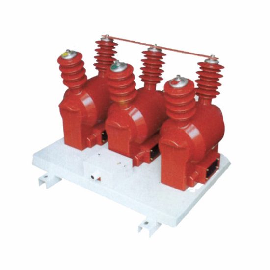
Introduction to the SZW-10R Current Transformer
The SZW-10R is a dry-type, cast-resin insulated current transformer engineered for precise current measurement and protective relaying in 11kV (IEC) / 10kV (domestic) medium-voltage power systems. Designed for indoor installation within metal-enclosed switchgear or open-frame substations, it delivers high accuracy under both steady-state and transient fault conditions. Its construction leverages vacuum pressure impregnation (VPI) epoxy resin technology, which fully encapsulates the magnetic core and windings, eliminating air voids and moisture ingress pathways.
Operating Principle of Cast-Resin Insulation
Cast-resin insulation in the SZW-10R employs a cycloaliphatic epoxy resin system cured under controlled temperature and vacuum conditions. This process ensures complete impregnation of the primary conductor, secondary windings, and GOES (grain-oriented electrical steel) core assembly. The resulting monolithic structure provides superior dielectric strength (≥30 kV/mm), excellent tracking resistance (CTI ≥600 V), and minimal partial discharge activity (<5 pC at 1.2 × Um/√3). Unlike oil-filled units, the solid insulation eliminates fire hazards, environmental contamination risks, and maintenance-intensive oil sampling.
Advantages Over Oil-Immersed Designs
The SZW-10R’s dry-type construction offers significant operational advantages: zero risk of oil leakage or flammability, reduced lifecycle costs due to minimal maintenance, lighter weight for easier handling, and immunity to altitude-related pressure differentials. Additionally, the thermal stability of epoxy resin allows continuous operation at ambient temperatures up to +40°C with short-term overload capability (up to 200% of rated current for 1 second). These attributes make it ideal for urban substations, commercial complexes, and industrial facilities where safety and space constraints are critical.
Typical Applications Overview
This CT model is predominantly deployed in ring main units (RMUs), pad-mounted switchgear, and indoor distribution substations operating at 11kV nominal voltage. It interfaces with revenue-class energy meters (accuracy class 0.2S/0.5S), protective relays (class 5P/10P), and SCADA systems. Its compact footprint and standardized mounting dimensions facilitate retrofitting into legacy infrastructure without major modifications, supporting grid modernization initiatives across Asia, Europe, and emerging markets adhering to IEC or GB standards.
Technical Specifications
The SZW-10R complies with stringent performance criteria defined by IEC 61869-2 and GB/T 20840.2. Key parameters ensure reliable operation across diverse environmental and electrical conditions.
| Parameter | Value |
|---|---|
| Rated Voltage (Um) | 12 kV (system 11kV IEC / 10kV domestic) |
| Primary Current (Ip) | 50–4000 A (standard ratios: e.g., 200/5, 600/1, 1000/5) |
| Secondary Current (Is) | 1 A or 5 A |
| Accuracy Classes | Metering: 0.2S, 0.5S; Protection: 5P10, 5P20, 10P10 |
| Rated Output (Burden) | 2.5–30 VA (per class and ratio) |
| Short-Time Thermal Current | 25 kA for 1 s (at 50 Hz) |
| Dynamic Withstand Current | 62.5 kA peak |
| Insulation Level (LI/AC) | 75 kV / 28 kV (1 min, 50 Hz) |
| Partial Discharge | <5 pC at 1.2 × 12/√3 kV |
Standard Service Conditions
The SZW-10R is rated for indoor use under normal service conditions per IEC 61869-1: ambient temperature range –5°C to +40°C (24-hour average ≤+35°C), relative humidity ≤95% non-condensing, and installation altitude ≤1000 m above sea level. For altitudes exceeding 1000 m, derating factors apply per IEC 60071-2—typically 1.5% reduction in withstand voltage per 100 m above 1000 m. The unit is not suitable for explosive atmospheres unless housed in certified enclosures.
Core and Winding Construction
The magnetic circuit utilizes high-permeability GOES laminations (grade M4 or equivalent) with low hysteresis loss, stacked and annealed to minimize remanence. Secondary windings are wound with oxygen-free copper wire, tightly layered and impregnated before final resin casting. Primary conductors are either solid busbar (for lower ratios) or multi-turn coils (for higher ratios), ensuring uniform current distribution and minimal stray flux. Terminal blocks feature screw-type connectors rated for 600 V and 20 A, compatible with standard 2.5–6 mm² instrumentation cables.
Typical Applications
The SZW-10R serves critical roles across multiple power infrastructure segments, delivering metrological integrity and protection reliability.
Substation Secondary Metering
In 11kV primary substations, the SZW-10R feeds Class 0.2S current inputs to revenue meters for accurate billing and load profiling. Its low phase displacement (<±10 minutes at 100% In) and ratio error (<±0.2%) ensure compliance with EN 50163 and DL/T 448 requirements. Installation typically occurs on outgoing feeders or transformer incomers, with secondary circuits routed through shielded twisted-pair cables to minimize electromagnetic interference from adjacent switchgear operations.
Industrial Power Distribution
Within manufacturing plants and data centers, the SZW-10R supports motor protection schemes using 5P20-class outputs to overcurrent and earth-fault relays. Its high saturation point (Vk ≥ 100 V for 5P20) guarantees correct relay operation during high-magnitude faults. The compact design fits within ANSI C37.20.2 switchgear cubicles, enabling seamless integration with digital multifunction relays like SEL-751 or Siemens 7SJ62.
Renewable Energy Integration
Solar PV and wind farms utilize the SZW-10R on 11kV collector feeders to monitor generation output and provide anti-islanding protection. The CT’s linear response under harmonic-rich waveforms (THD ≤15%) ensures accurate metering despite inverter-induced distortion. Its robust insulation withstands frequent switching transients from capacitor banks used for reactive power compensation.
Rural and Suburban Distribution Networks
In utility-owned RMUs serving residential areas, the SZW-10R enables remote fault detection via SCADA-linked protection relays. Its maintenance-free design reduces outage durations in hard-to-access locations. Standardized 600/5 or 400/1 ratios align with regional grid codes, facilitating interoperability across mixed-vendor networks.
Grid Modernization Retrofits
Legacy 10kV networks upgrading to smart grid architectures often replace oil-filled CTs with SZW-10R units due to dimensional compatibility and enhanced safety. The absence of oil simplifies disposal logistics during decommissioning, aligning with RoHS and WEEE directives.
Compliance with International Standards
The SZW-10R is engineered and tested to meet dual compliance with global and Chinese national standards, ensuring broad market acceptance.
IEC 61869-2 Certification Requirements
Per IEC 61869-2:2012, the SZW-10R undergoes type tests including temperature rise (≤60 K for windings), short-circuit withstand (25 kA/1s), and accuracy verification across 1–120% of rated current. Routine tests—insulation resistance (>1000 MΩ at 500 V DC), turns ratio (±0.25% tolerance), and polarity—are performed on every unit. The manufacturer must maintain ISO 9001-certified quality control with traceable calibration to national metrology institutes.
Alignment with GB/T 20840.2
GB/T 20840.2-2014 mirrors IEC 61869-2 but includes additional requirements for Chinese grid operators: mandatory seismic testing (horizontal acceleration 0.2g), stricter partial discharge limits (<3 pC), and extended thermal endurance (1.1 × In for 8 hours). The SZW-10R meets these via reinforced core clamping and optimized resin formulation, validated by CNAS-accredited laboratories.
Key Differences Between IEC and GB Standards
While both standards define similar accuracy classes, GB/T 20840.2 mandates higher short-circuit ratings for certain applications (e.g., 31.5 kA/1s in urban zones) and requires flame-retardant resin (UL94 V-0 rating). IEC focuses more on environmental adaptability (e.g., pollution degree 3), whereas GB emphasizes mechanical robustness for high-seismic regions. Dual-certified units like the SZW-10R undergo hybrid test protocols covering all divergent clauses.
On-Site Testing Procedures
Post-installation verification ensures the SZW-10R performs within specification before energization. All tests follow IEEE C57.13.6 and IEC 61869-2 guidelines.
Insulation Resistance Test
Using a 500 V DC megohmmeter, measure resistance between primary-to-secondary, primary-to-ground, and secondary-to-ground. Acceptance criterion: ≥1000 MΩ at 25°C. Correct for temperature using RT2 = RT1 × 2(T1–T2)/10. Low readings indicate moisture ingress or resin cracking—requiring drying or replacement.
Turns Ratio Test
Apply a low-voltage AC source (5–10 V) to the secondary winding and measure induced primary voltage. Calculate ratio as Vp/Vs; compare to nameplate. Tolerance: ±0.25% for metering classes, ±1% for protection. Use a dedicated ratio tester (e.g., Omicron CT Analyzer) for automated comparison. Deviations suggest winding shorts or incorrect tap selection.
Polarity Verification
Confirm reducing polarity (IEC standard) using the DC kick method: momentarily connect a 6 V battery across secondary terminals (P1 to +, P2 to –). A DC voltmeter on primary should show a positive deflection on closure. Incorrect polarity causes relay misoperation—critical in differential schemes. Digital testers automate this via phase-angle measurement (<±2° error).
Power Frequency Withstand Voltage Test
Apply 28 kV RMS (50 Hz) for 1 minute between primary and grounded secondary/core. Leakage current must remain <1 mA. Gradually ramp voltage to avoid transient overstress. Failure indicates insulation degradation. For field testing, use portable AC hipot sets with overcurrent trip settings at 5 mA.
Short-Circuit Test (CT-Specific)
Unlike VTs, CTs require secondary short-circuit verification. Ensure secondary terminals are bridged before primary energization to prevent dangerous overvoltages. Measure secondary current under 10–20% primary load; verify linearity against nameplate burden. Open-circuit operation must be strictly avoided—permanent core damage occurs above 500 V induced EMF.
Preventive Maintenance Guide
Although cast-resin CTs are largely maintenance-free, periodic checks extend service life and prevent unexpected failures.
Annual Visual and Electrical Inspection
Inspect for surface cracks, tracking marks, or discoloration on the resin housing. Clean with dry cloth—never solvents. Verify terminal tightness (torque: 1.5 N·m for M4 screws). Re-measure insulation resistance and compare to baseline values; a 50% drop warrants further investigation. Check secondary circuit continuity and grounding integrity (resistance <0.1 Ω).
Five-Year Comprehensive Maintenance
Perform full re-validation of accuracy class using a portable calibrator (e.g., Doble M4100). Test ratio error and phase displacement at 1%, 5%, 20%, 100%, and 120% of rated current. Inspect mounting hardware for corrosion. Update asset records with test results. If installed in high-humidity environments, consider infrared thermography to detect localized heating under load.
Fault Diagnosis and Troubleshooting
| Symptom | Possible Cause | Remedial Action |
|---|---|---|
| High ratio error | Core saturation, winding short | Demagnetize core; if persistent, replace CT |
| Low insulation resistance | Surface contamination, moisture | Clean and dry; retest after 24h |
| Abnormal noise/vibration | Loose core laminations | Check mounting; if internal, replace unit |
| Relay misoperation | Incorrect polarity, burden mismatch | Verify wiring; confirm burden ≤ rated VA |
Conclusion
The SZW-10R 11kV cast-resin current transformer represents a benchmark in reliability, accuracy, and safety for medium-voltage applications. Its epoxy-encapsulated design eliminates the fire and environmental hazards associated with oil-filled alternatives while delivering metrological precision compliant with IEC 61869-2 and GB/T 20840.2. The use of GOES silicon steel cores ensures low losses and high saturation margins, critical for protection-grade performance during fault transients. With a design life of 25–30 years under standard operating conditions, the SZW-10R minimizes total cost of ownership through near-zero maintenance requirements and resilience to harsh electrical environments. Its compatibility with modern digital relays and metering systems makes it an essential component in both greenfield installations and legacy grid upgrades. Adherence to rigorous factory and field testing protocols guarantees consistent performance, supporting grid stability and accurate energy accounting across diverse global markets.
Frequently Asked Questions (FAQ)
Q1: Can the SZW-10R be used in outdoor switchgear?
No. The SZW-10R is rated for indoor use only (IP00). Outdoor applications require weatherproof housings or alternative models with IP54+ enclosures.
Q2: What is the maximum allowable secondary burden for a 0.2S class SZW-10R?
Burden depends on ratio—e.g., 200/5 A: max 10 VA; 1000/5 A: max 30 VA. Exceeding rated burden degrades accuracy beyond class limits.
Q3: How often should insulation resistance be tested?
Annually during routine substation maintenance. After any fault event or prolonged moisture exposure, immediate testing is recommended.
Q4: Is demagnetization required after a fault?
Yes. High fault currents can leave residual magnetism, increasing ratio error. Demagnetize using a variable AC source decaying from 120% to 0% over 30 seconds.
Q5: Can multiple secondary windings share a common core?
Yes—the SZW-10R offers dual-core variants (e.g., 0.2S for metering + 5P20 for protection) with magnetically isolated windings to prevent cross-interference.
Q6: What torque should be used on secondary terminals?
1.5 N·m for M4 screw terminals. Over-torquing risks thread stripping; under-torquing causes overheating due to poor contact.