Article Content
Introduction to the UTF-8 Voltage Transformer
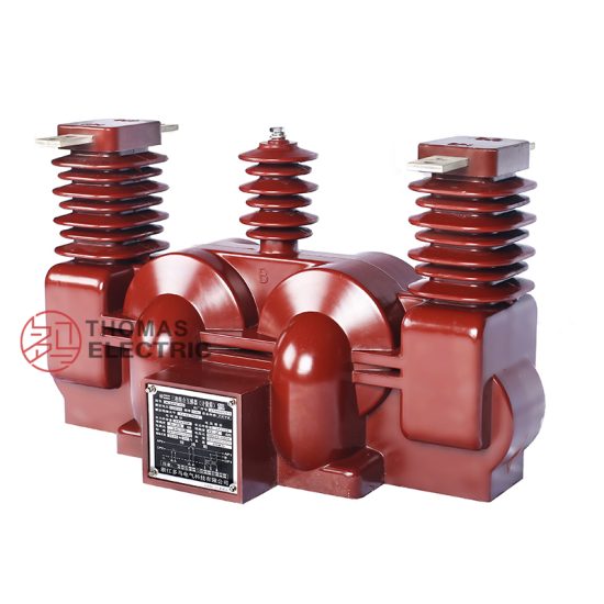
The UTF-8 is a single-phase, cast-resin insulated voltage transformer (VT) designed for accurate voltage measurement and reliable protection signaling in medium-voltage power systems operating at 11kV (IEC standard) or 10kV (domestic Chinese system). Engineered in strict compliance with IEC 61869-3 and GB/T 20840.3, this instrument transformer leverages advanced vacuum pressure impregnation (VPI) epoxy resin technology to encapsulate its magnetic core and windings, delivering superior dielectric strength, environmental resilience, and long-term operational stability.
Unlike traditional oil-immersed VTs, which pose fire hazards, require containment systems, and suffer from oil degradation over time, the UTF-8’s solid cast-resin construction eliminates flammable materials, reduces maintenance overhead, and enables safe deployment in both indoor switchgear and outdoor substations—even in polluted or high-humidity environments. The absence of liquid insulation also prevents leakage risks and simplifies transportation and handling during installation.
Primary applications include revenue metering, protective relaying, synchro-checking, and power quality monitoring in distribution networks ranging from urban substations to industrial facilities and renewable energy interconnection points. Its compact footprint and robust mechanical design make it particularly suitable for space-constrained installations where reliability and precision are non-negotiable.
Operating Principle and Insulation Technology
The UTF-8 operates on the fundamental principle of electromagnetic induction: the primary winding, connected across the 11kV line-to-ground voltage, induces a proportional secondary voltage in the isolated secondary winding(s). This scaled-down signal—typically 100 V or 100/√3 V—is then used by meters, relays, or control devices. The core is fabricated from grain-oriented electrical steel (GOES), selected for its low core loss (<0.8 W/kg at 1.7 T, 50 Hz) and high permeability, ensuring minimal phase displacement and ratio error under normal and transient conditions.
Critical to performance is the VPI cast-resin insulation system. During manufacturing, the wound core assembly undergoes vacuum drying to remove moisture, followed by impregnation under pressure with a cycloaliphatic epoxy resin formulation. This process fully penetrates inter-turn and inter-layer voids, creating a monolithic, void-free structure with a dielectric strength exceeding 20 kV/mm. The resulting composite exhibits excellent tracking resistance (CTI > 600 V), UV stability, and thermal endurance up to 130°C (Class B insulation), enabling continuous operation in ambient temperatures from -40°C to +40°C.
Advantages Over Oil-Immersed Designs
Cast-resin VTs like the UTF-8 offer distinct technical and operational advantages over oil-filled counterparts. First, they are inherently fire-resistant (IEC 60695 glow-wire tested to 850°C), eliminating the need for fire barriers or oil containment pits—critical for indoor GIS or urban substations. Second, the solid insulation is immune to oxidation, moisture ingress, and gas evolution, ensuring stable dielectric properties over decades without periodic oil testing or replacement. Third, the mechanical rigidity of the epoxy matrix dampens vibration and acoustic noise, reducing audible hum to below 45 dB(A) at rated voltage.
Additionally, the UTF-8’s lightweight design (approximately 45–55 kg depending on configuration) simplifies logistics and mounting compared to heavier oil units. Environmental compliance is enhanced: no PCBs, no hydrocarbon emissions, and full recyclability of metallic components at end-of-life. These attributes collectively reduce total cost of ownership while meeting stringent safety codes such as IEC 61439 for switchgear assemblies.
Technical Specifications
The UTF-8 voltage transformer is engineered to deliver precise performance under defined service conditions. Below is a comprehensive specification table aligned with IEC 61869-3 requirements:
| Parameter | Value |
|---|---|
| System Voltage (IEC) | 11 kV |
| System Voltage (Domestic) | 10 kV |
| Primary Voltage (Up) | 11 / √3 kV (line-to-ground) |
| Secondary Voltage(s) | 100 / √3 V (metering), 100 V (protection) |
| Voltage Ratio | 11000/√3 : 100/√3 : 100 |
| Accuracy Class (Metering) | 0.2 / 0.5 |
| Accuracy Class (Protection) | 3P / 6P |
| Rated Output (per winding) | 30 VA (0.2 class), 50 VA (0.5 class), 100 VA (3P/6P) |
| Insulation Level (LI/AC) | 75 kV / 28 kV (1 min) |
| Short-Time Thermal Withstand | 1 s at 10× rated secondary current (for burden faults) |
| Frequency | 50 Hz ± 0.5 Hz |
| Core Material | GOES (Grain-Oriented Electrical Steel), M4 grade |
| Insulation System | VPI Cast Epoxy Resin, Class B (130°C) |
| IP Rating | IP00 (for switchgear integration); IP23 with optional terminal box |
Standard Service Conditions
The UTF-8 is rated for standard service conditions per IEC 60060-1 and IEC 61869-3: ambient temperature range of -40°C to +40°C, relative humidity up to 100% (condensing permitted), and installation altitude not exceeding 1000 m above sea level. For altitudes between 1000 m and 3000 m, derating factors apply to the insulation withstand voltage—typically a 1% reduction per 100 m above 1000 m. The transformer is designed for continuous operation under nominal system frequency (50 Hz) with harmonic distortion not exceeding 5% THD. Transient overvoltages up to 1.2 × Um (13.2 kV) are permissible for short durations without degradation.
Mechanical loads are limited to static forces from busbar connections; dynamic short-circuit forces are absorbed by the rigid epoxy housing. The unit must be mounted vertically with primary terminals facing upward to ensure proper creepage distance and thermal convection. Grounding of the core and enclosure is mandatory via a dedicated M10 stud with ≤0.1 Ω resistance to earth.
Accuracy and Burden Characteristics
Ratio error and phase displacement are guaranteed within IEC 61869-3 limits across the specified accuracy classes. For example, at 0.2 class and 25–100% of rated burden, ratio error must not exceed ±0.2%, and phase error must be ≤±10 minutes. At 3P protection class, ratio error is limited to ±3% from 1–100% of rated voltage. Burden must be purely resistive-inductive (power factor 0.8 lagging); capacitive burdens can induce ferroresonance and are prohibited unless damped by a parallel resistor ≥300 Ω.
The dual-secondary design allows independent metering and protection circuits. Overloading beyond 120% of rated VA for more than 8 hours may cause thermal drift or permanent accuracy shift. Continuous operation at 150% burden is permissible only for fault-duration periods (≤10 s).
Typical Applications
The UTF-8 cast-resin voltage transformer serves critical roles across diverse power infrastructure segments, leveraging its precision, safety, and durability.
Substation Secondary Metering
In 11kV/10kV distribution substations, the UTF-8 provides the reference voltage signal for revenue-grade kWh meters, demand recorders, and power quality analyzers. Its 0.2-class accuracy ensures billing compliance per regulatory standards (e.g., DL/T 448 in China). The metering secondary (100/√3 V) feeds into three-phase metering cabinets, while the protection secondary (100 V) connects to overvoltage, undervoltage, and directional earth-fault relays. The transformer’s low phase error (<5 minutes at 0.2 class) minimizes vector group mismatches in synchrophasor applications. Installation within metal-enclosed switchgear (e.g., RMU or AIS) benefits from the VT’s compact size and arc-resistant housing.
Industrial Power Distribution
Large industrial facilities—such as chemical plants, data centers, and manufacturing complexes—use the UTF-8 for internal energy management and motor protection schemes. In motor control centers (MCCs), it supplies voltage signals to soft starters, VFDs, and protection relays (e.g., SEL-751) for phase-loss and reverse-power detection. The cast-resin design resists chemical fumes and dust common in industrial environments, unlike oil units that degrade seals. Dual outputs enable simultaneous connection to SCADA systems (via RTUs) and local HMI panels without burden sharing compromises.
Renewable Energy Integration
Solar PV farms and wind parks connecting to 10kV/11kV grids rely on the UTF-8 for grid-synchronization and anti-islanding protection. During islanding events, rapid voltage deviation detection (<20 ms response) by relays using the UTF-8’s 100 V output triggers disconnection per IEEE 1547 or GB/T 19964. The VT’s immunity to DC offset (from inverter harmonics) and high-frequency transients ensures stable operation during cloud-induced irradiance swings or turbine gust responses. Its outdoor rating (with UV-stabilized resin) supports pole-mounted or pad-mounted inverter station deployments.
Rural and Suburban Distribution Networks
In remote or semi-urban areas with limited maintenance access, the UTF-8’s maintenance-free design is ideal. It replaces aging oil-filled VTs on pole-top transformers or underground ring main units (RMUs), providing voltage signals for automated feeder reclosers and sectionalizers. The 6P protection class tolerates wide voltage fluctuations common in weak rural grids (e.g., 8–12 kV swings), maintaining relay coordination during faults. Its lightweight nature simplifies helicopter or manual pole installation in mountainous terrain.
Compliance with International Standards
The UTF-8 voltage transformer is certified to meet the rigorous requirements of both international and domestic standards, ensuring interoperability and safety across global markets.
IEC 61869-3 Compliance Details
IEC 61869-3 specifies performance, testing, and marking requirements for inductive voltage transformers. The UTF-8 complies fully with Clause 5 (rated values), Clause 6 (accuracy requirements), and Clause 7 (tests). Key verified parameters include: thermal stability under 1.2 × Up for 8 hours, partial discharge levels <10 pC at 1.2 × Um/√3, and impulse withstand capability of 75 kV (1.2/50 μs wave). Type tests—including temperature rise, short-circuit, and seismic tests—are conducted at accredited laboratories (e.g., KEMA or CESI) and documented in the test report supplied with each unit. Routine tests per Clause 12 (ratio, polarity, insulation resistance) are performed on 100% of production units.
Alignment with GB/T 20840.3
GB/T 20840.3 is the Chinese national adoption of IEC 61869-3, with minor modifications for domestic grid practices. The UTF-8 meets all GB-specific requirements, including: primary voltage rating of 10 kV (system) with Um = 12 kV, creepage distance ≥240 mm/kV for pollution class III, and mandatory flame retardancy per GB/T 5169.11. Notably, GB/T 20840.3 permits slightly wider ratio error tolerances at light loads (e.g., ±0.3% at 1 VA for 0.2 class vs. IEC’s ±0.2%), but the UTF-8 exceeds both standards. Certification is issued by CQC (China Quality Certification Center) with annual factory audits.
Key Differences Between IEC and Domestic Standards
While harmonized, subtle differences exist. IEC 61869-3 defines system voltage as 11 kV (Un), whereas GB/T 20840.3 uses 10 kV—though both reference the same maximum system voltage Um = 12 kV. Insulation coordination differs: IEC uses LI/AC = 75/28 kV, while GB often specifies 95/35 kV for 10 kV systems in high-lightning areas; however, the UTF-8’s design margin accommodates both. Accuracy verification burden in GB includes 1.2 × rated VA, whereas IEC uses 1.0 ×. Crucially, GB mandates additional salt fog testing (48 h, 5% NaCl) for coastal deployments—a test the UTF-8 passes due to its hydrophobic resin surface.
On-Site Testing Procedures
Post-installation and periodic field testing ensures the UTF-8 operates within design parameters. All tests must follow IEC 60060-1 and IEC 61869-10 procedures.
Insulation Resistance Test
Measure insulation resistance between primary winding and ground, and between primary and secondary windings, using a 2500 V DC megohmmeter. Acceptance criteria: ≥1000 MΩ at 20°C. Correct for temperature using RT2 = RT1 × 2(T1−T2)/10. Values below 500 MΩ indicate moisture ingress or resin cracking and require drying or replacement. Perform before and after any withstand test to detect insulation degradation.
Turns Ratio Test
Apply a low-voltage AC source (50–200 V) to the primary and measure secondary voltage with a calibrated voltmeter (±0.1% accuracy). Calculate actual ratio and compare to nameplate. Tolerance: ±0.2% for 0.2 class, ±0.5% for 0.5 class, ±3% for 3P. Use a dedicated ratio tester (e.g., Omicron CT Analyzer) for automatic comparison. Deviations > tolerance suggest turn-to-turn shorts or winding damage.
Polarity Test
Verify reducing polarity per IEC 61869-1 Annex A. Connect a 6–12 V battery across primary terminals (H1+, H2−). Momentarily close the circuit and observe a DC voltmeter connected to secondary (X1+, X2−). A positive kick confirms correct polarity. Incorrect polarity causes 180° phase reversal, leading to metering errors or relay misoperation. Document results in commissioning reports.
Power Frequency Withstand Voltage Test
Apply 28 kV RMS (50 Hz) for 1 minute between primary and grounded secondary/core. Use a calibrated test transformer with overcurrent trip set at 10 mA. No flashover or breakdown is acceptable. Reduce voltage gradually post-test. This verifies integrity after transport or installation stress. Do not perform if insulation resistance is <1000 MΩ.
Open-Circuit Characteristic Test
For VTs, the open-circuit test assesses core saturation and excitation current. Apply 10–130% of rated primary voltage (in 10% steps) to the primary with secondaries open. Measure excitation current; it should increase non-linearly above 110% Up. At 190% Up (for 30 s), current must remain below 10× rated excitation. Excessive current indicates core defects or shorted laminations.
Preventive Maintenance Guide
Although cast-resin VTs are largely maintenance-free, scheduled inspections prevent unexpected failures.
Periodic Visual and Electrical Inspection
Conduct annual visual checks for: surface cracks, tracking marks, terminal corrosion, or loose hardware. Clean with dry cloth; avoid solvents. Electrically, repeat insulation resistance and ratio tests annually. Monitor secondary voltage under load—if deviation exceeds 0.5% from baseline, investigate burden changes or internal faults. In coastal or industrial zones, inspect every 6 months for salt or chemical deposits.
Long-Term Maintenance Schedule
Every 5 years, perform a full diagnostic suite: partial discharge measurement (<20 pC at 1.2 × Um/√3), tan delta test (loss angle <0.5% at 10 kV), and thermal imaging under load (ΔT <15°C vs. ambient). Replace surge arresters connected to the VT if leakage current exceeds 0.5 mA. After severe system faults (e.g., close-in short circuits), conduct immediate post-event testing regardless of schedule.
Fault Diagnosis and Troubleshooting
Common issues include: blown secondary fuses (indicating burden short), erratic meter readings (polarity error or ratio shift), or overheating (excessive burden or harmonic resonance). Use an oscilloscope to check for ferroresonance (irregular voltage waveforms)—install damping resistors if observed. If insulation resistance drops persistently, the unit likely has internal moisture and should be retired. Never attempt field repair of cast-resin units; replace entirely.
| Interval | Task | Acceptance Criteria |
|---|---|---|
| Annual | Visual inspection, IR test, ratio test | IR ≥1000 MΩ; ratio within class tolerance |
| 5-Year | PD test, tan delta, thermal scan | PD <20 pC; tan δ <0.5%; ΔT <15°C |
| Post-Fault | Full electrical test suite | No degradation vs. baseline |
Conclusion
The UTF-8 11kV cast-resin voltage transformer represents a benchmark in medium-voltage instrumentation, combining precision engineering with robust environmental performance. Its VPI epoxy resin insulation system, coupled with a GOES silicon steel core, delivers exceptional dielectric strength, thermal stability, and long-term accuracy—critical for both revenue metering and protection applications. By adhering strictly to IEC 61869-3 and GB/T 20840.3, the UTF-8 ensures global compatibility while exceeding domestic reliability expectations. Unlike oil-immersed alternatives, it eliminates fire risk, reduces lifecycle costs, and withstands harsh conditions from arid deserts to humid coastal zones. With a design life of 25–30 years under standard service conditions, the UTF-8 minimizes replacement cycles and supports sustainable grid infrastructure. Its dual-secondary configuration, compact form factor, and rigorous factory testing make it the preferred choice for modern substations, industrial complexes, and renewable integration projects worldwide. Proper on-site testing and preventive maintenance—as detailed in this guide—further guarantee decades of trouble-free operation, reinforcing the transformer’s role as a cornerstone of power system integrity and safety.
Frequently Asked Questions (FAQ)
Q1: Can the UTF-8 be used on a 10kV domestic system?
Yes. While rated for 11kV per IEC standards, the UTF-8 is fully compatible with 10kV Chinese distribution systems (Um = 12 kV). Its insulation level (75/28 kV) exceeds GB requirements for 10kV networks.
Q2: What is the minimum burden required to prevent ferroresonance?
A minimum resistive burden of 30 VA (at 0.8 pf lagging) is recommended. For unloaded secondaries, install a permanently connected damping resistor of 300–500 Ω across the terminals.
Q3: How often should insulation resistance be tested?
Annually under normal conditions. In high-humidity, high-pollution, or post-fault scenarios, test every 6 months or immediately after the event.
Q4: Is the UTF-8 suitable for indoor GIS applications?
Yes. Its fire-resistant, non-outgassing cast-resin construction meets IEC 62271-200 requirements for gas-insulated switchgear. Ensure adequate creepage clearance per pollution class.
Q5: What happens if the secondary is left open-circuited?
Unlike CTs, VT secondaries can be open—but prolonged no-load operation increases core flux density, raising excitation current and risk of overheating. Always connect a minimum burden or damping resistor.
Q6: Does Duomatech provide calibration certificates?
Yes, traceable to NIM (China) or PTB (Germany) standards, included with every unit. Recalibration is recommended every 5 years.
Q7: Can multiple UTF-8 units share a common grounding point?
Yes, but use a star grounding topology with individual leads to a single earth bar. Avoid daisy-chaining to prevent circulating currents and ground potential rise errors.