Article Content
11kV Cast-Resin Current Transformer ZZW-35 for Metering and Protection – IEC 61869-2 Standard
Introduction to the ZZW-35 Current Transformer
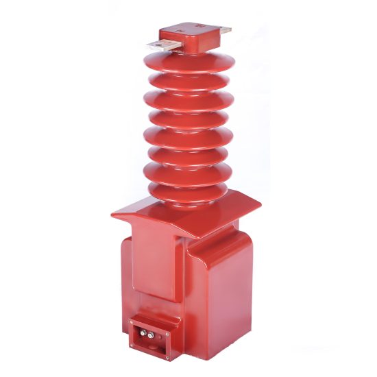
The ZZW-35 is a medium-voltage cast-resin current transformer (CT) engineered for reliable operation in 11kV (IEC) / 10kV (domestic) power systems. Designed in strict compliance with IEC 61869-2 and GB/T 20840.2, this instrument transformer provides accurate current transformation for metering, protection, and monitoring functions while ensuring galvanic isolation between high-voltage primary circuits and low-voltage secondary instrumentation. Its robust construction leverages modern epoxy resin vacuum pressure impregnation (VPI) technology, offering superior dielectric strength, environmental resilience, and long-term stability compared to legacy oil-filled or dry-type alternatives.
Operating Principle of Cast-Resin Insulation
Cast-resin insulation in the ZZW-35 utilizes a cycloaliphatic epoxy resin system processed under vacuum and pressure to fully impregnate the primary conductor, secondary windings, and magnetic core assembly. This VPI technique eliminates air voids and moisture ingress pathways, resulting in homogeneous dielectric properties and enhanced partial discharge resistance (<5 pC at 1.2 × Ur). The resin matrix bonds molecularly with embedded components, creating a monolithic structure that withstands thermal cycling from –40°C to +40°C without cracking or delamination. Unlike oil-immersed CTs, the solid insulation eliminates fire hazards, leakage risks, and maintenance-intensive oil sampling—critical advantages in indoor substations, urban switchgear, and environmentally sensitive zones. The resin’s high tracking index (>600 V) ensures surface flashover resistance even under pollution class III conditions.
Advantages Over Oil-Immersed Designs
The ZZW-35’s cast-resin construction delivers multiple operational benefits over traditional oil-filled CTs. First, it requires zero fluid maintenance—no oil level checks, degassing, or dielectric testing of insulating liquid. Second, its compact footprint (typically 30–40% smaller than equivalent oil units) simplifies integration into space-constrained ring main units (RMUs) or metal-enclosed switchgear. Third, the absence of flammable oil meets stringent fire safety codes (e.g., IEC 62271-200) for indoor installations near personnel or critical infrastructure. Additionally, the epoxy resin exhibits excellent UV and ozone resistance, enabling reliable outdoor deployment without protective housings. Thermal performance is also superior: the resin’s thermal conductivity (~0.8 W/m·K) efficiently dissipates heat from copper windings during overload or fault conditions, maintaining accuracy class integrity up to 120% of rated continuous current.
Typical Applications Overview
The ZZW-35 serves as a foundational component in diverse 11kV distribution networks. In utility substations, it feeds revenue-grade metering systems (Class 0.2S or 0.5S) and high-speed protection relays (Class 5P or 10P). Industrial facilities deploy it for motor protection, arc-flash mitigation, and energy management in 10kV plant distribution. Renewable energy projects—particularly solar farms and wind substations—use the ZZW-35 for grid interconnection metering and anti-islanding protection due to its stable ratio error (<±0.1% at 100% In) and phase displacement (<±5 minutes). Rural electrification schemes benefit from its maintenance-free operation and tolerance to wide ambient temperature swings. Its dual-ratio or multi-tap secondary windings support flexible configuration for both metering and protection on a single unit, reducing equipment count and lifecycle costs.
Technical Specifications
The ZZW-35 is engineered to meet rigorous electrical and environmental performance criteria defined by international and domestic standards. Below is a representative specification table based on typical configurations; actual parameters may vary by customer order.
| Parameter | Value |
|---|---|
| Rated Voltage (Ur) | 11 kV (IEC) / 10 kV (GB) |
| Primary Current (Ip) | 50 A to 3000 A (standard); up to 5000 A (custom) |
| Secondary Current (Is) | 1 A or 5 A |
| Accuracy Classes | Metering: 0.2S, 0.5S; Protection: 5P10, 5P20, 10P10, 10P20 |
| Rated Output (Burden) | 2.5 VA to 30 VA (per IEC 61869-2) |
| Insulation Level | Power Frequency Withstand: 28 kV rms / 1 min Lightning Impulse Withstand: 75 kV peak |
| Short-Time Thermal Current | 25 kA for 1 s (Ith) |
| Dynamic Withstand Current | 62.5 kA peak (Idyn) |
| Ambient Temperature Range | –40°C to +40°C |
| Altitude Limit | ≤ 1000 m above sea level (derating required >1000 m) |
| Relative Humidity | Up to 95% non-condensing |
| Core Material | Grain-Oriented Electrical Steel (GOES), CRGO grade |
Standard Service Conditions
The ZZW-35 is rated for standard service conditions per IEC 61869-2: ambient temperature range of –40°C to +40°C, relative humidity up to 95% (non-condensing), and installation altitude not exceeding 1000 meters. At altitudes above 1000 m, the external insulation must be derated by 1% per 100 m increment for both power frequency and lightning impulse tests. For example, at 2000 m, the power frequency withstand voltage reduces from 28 kV to 25.2 kV. The transformer is suitable for both indoor and outdoor use; however, outdoor installations require mounting under shelter or with drip shields to prevent direct water accumulation on terminals. Pollution degree is classified as III, meaning it tolerates conductive dust, rain, and snow without performance degradation—verified through salt fog and dew tests per IEC 60507.
Electrical Performance Parameters
Key electrical characteristics ensure precision and reliability across operating ranges. Ratio error at rated current (In) must not exceed ±0.1% for Class 0.2S and ±0.2% for Class 0.5S under burdens from 25% to 100% of rated VA. Phase displacement remains within ±5 minutes (0.2S) and ±10 minutes (0.5S). For protection classes, the composite error at specified accuracy limit factor (e.g., 10 for 5P10) must be ≤5%. The secondary winding DC resistance typically ranges from 0.05 Ω (5 A output) to 1.2 Ω (1 A output), influencing burden calculations. Saturation flux density of the GOES core exceeds 1.8 T, enabling linear response up to 20× In during fault transients. Partial discharge levels are guaranteed below 5 pC at 1.2 × Ur, ensuring long-term insulation integrity.
Typical Applications
The ZZW-35’s versatility makes it indispensable across modern power infrastructure. Its dual-role capability—supporting both high-accuracy metering and robust protection—reduces capital expenditure and simplifies system design.
Substation Secondary Metering
In 11kV/0.4kV distribution substations, the ZZW-35 supplies Class 0.2S or 0.5S secondary currents to revenue meters compliant with IEC 62053-22. Its low ratio error ensures billing accuracy even at light loads (down to 1% In), critical for commercial and industrial consumers. The CT is typically installed on the incoming feeder or outgoing circuit breakers, with secondary leads routed to a metering cabinet via shielded twisted-pair cables to minimize electromagnetic interference. For three-phase systems, matched sets (same batch, same ratio) are recommended to maintain vector group consistency. The ZZW-35’s stable thermal performance prevents drift during summer peak loads, where ambient temperatures can exceed 35°C in unventilated enclosures.
Industrial Power Distribution
Manufacturing plants and data centers operating on 10kV internal distribution rely on the ZZW-35 for motor protection, feeder monitoring, and arc-flash hazard mitigation. Protection-class windings (e.g., 5P20) feed digital relays that detect ground faults, phase imbalances, or overloads within milliseconds. The CT’s high dynamic withstand (62.5 kA) ensures mechanical survival during bolted faults common in industrial networks with low impedance. In hazardous areas (e.g., chemical plants), the absence of oil eliminates explosion risks, satisfying ATEX and IECEx requirements when paired with appropriate enclosures. Multi-ratio models allow a single CT to serve both local SCADA (1 A output) and backup electromechanical relays (5 A output), streamlining spare parts inventory.
Renewable Energy Integration
Solar photovoltaic (PV) and wind farm substations integrate the ZZW-35 at the point of common coupling (PCC) for grid compliance monitoring. It provides inputs to power quality analyzers measuring harmonics, flicker, and reactive power per EN 50160. During islanding events, the CT’s fast response enables anti-islanding relays to disconnect generation within 2 seconds. The cast-resin body resists thermal shock from rapid irradiance changes in desert climates, where daytime temperatures exceed 45°C and nighttime drops to 5°C. For offshore wind applications, enhanced hydrophobic coatings on the resin surface prevent salt deposition-induced flashovers. Dual-core designs (one for metering, one for protection) are standard to meet grid code separation requirements.
Rural and Suburban Distribution Networks
In rural electrification projects, the ZZW-35’s maintenance-free operation reduces O&M costs over decades-long deployments. Mounted on pole-top reclosers or pad-mounted switchgear, it endures monsoons, dust storms, and wide diurnal temperature swings without recalibration. Its compact size allows retrofitting into legacy 10kV networks originally designed for larger oil CTs. Utilities often specify 5 A secondary outputs to match existing electromechanical relays in aging infrastructure. The high short-time thermal rating (25 kA/1s) accommodates increasing fault levels from distributed generation interconnections. Field experience shows >99.5% reliability over 15 years in Southeast Asian and African deployments.
Compliance with International Standards
The ZZW-35 is certified to both global and Chinese national standards, ensuring interoperability and regulatory acceptance across markets.
IEC 61869-2 Compliance Details
IEC 61869-2 governs the performance, testing, and marking of instrument transformers for AC systems. The ZZW-35 meets all mandatory clauses, including type tests (insulation, temperature rise, short-circuit), routine tests (ratio, polarity, insulation resistance), and special tests (partial discharge, capacitance/tan δ). Key compliance aspects include: ratio error and phase displacement measured at 5%, 20%, 100%, and 120% of rated current; thermal stability verified at 1.2 × In for 8 hours; and dynamic force withstand validated via impulse current injection. Every unit undergoes factory routine testing per Clause 10, with test reports traceable to ISO/IEC 17025-accredited labs. Markings include Ur, Ip/Is, accuracy class, burden, and manufacturer ID per Clause 12.
GB/T 20840.2 Alignment
GB/T 20840.2 is China’s national adoption of IEC 61869-2, with minor modifications for domestic grid practices. The ZZW-35 complies fully, including the use of 10kV as the nominal system voltage (vs. 11kV IEC). Differences include: GB permits slightly higher ratio error tolerance at 1% In for Class 0.2S (+0.3% vs. IEC’s +0.2%), and requires additional seismic testing (0.3g horizontal acceleration) for units destined for earthquake-prone regions like Sichuan. Burden notation uses “VA” instead of “Ω,” aligning with Chinese utility preferences. All materials meet RoHS 2 (EU) and China RoHS requirements, with lead-free solder and halogen-free resin formulations.
Testing and Certification Requirements
Certification involves third-party validation by bodies such as KEMA, CESI, or CEPREI. Type tests are performed once per design variant and include: power frequency withstand (28 kV/1 min), lightning impulse (75 kV BIL), temperature rise (<60 K for windings), and short-circuit (25 kA/1s). Routine tests occur on 100% of production units: insulation resistance (>1000 MΩ at 500 V DC), turns ratio (±0.1% tolerance), polarity (reducing polarity confirmed), and secondary winding continuity. Special tests like partial discharge mapping are conducted quarterly on sample batches. Certificates list test voltages, ambient conditions, and pass/fail criteria, enabling utilities to verify compliance during procurement audits.
On-Site Testing Procedures
Post-installation and periodic field testing ensure the ZZW-35 performs within specifications throughout its service life.
Insulation Resistance Test
Measure insulation resistance between primary-to-secondary, primary-to-ground, and secondary-to-ground using a 500 V DC megohmmeter. Acceptance criterion: ≥1000 MΩ at 20°C. Correct for temperature using RT2 = RT1 × 2(T1–T2)/10. Low readings (<100 MΩ) indicate moisture ingress or resin cracking—common after prolonged exposure to condensation in unheated cabinets. Always discharge windings for 5 minutes post-test to prevent residual charge hazards. This test is mandatory after transportation or extended storage.
Turns Ratio Test
Apply a low-voltage AC source (e.g., 120 V) to the primary and measure secondary voltage. Calculate ratio as Vp/Vs; compare to nameplate Ip/Is. Tolerance: ±0.1% for metering classes, ±0.5% for protection. Use a dedicated ratio tester (e.g., Omicron CT Analyzer) for accuracy. Deviations >1% suggest turn-to-turn shorts or incorrect tap selection. Perform at multiple taps if multi-ratio. Ensure secondary burden is disconnected during test to avoid loading errors.
Polarity Test
Verify reducing polarity using the DC kick method: connect a 9 V battery momentarily between P1 and P2; observe galvanometer deflection on S1–S2. A positive kick confirms correct polarity (S1 corresponds to P1). Incorrect polarity causes relay misoperation—e.g., directional overcurrent relays tripping for reverse power flow. Digital testers automate this via phase angle measurement; acceptable phase shift: 0° ±2°. Polarity errors are common after terminal rewiring during maintenance.
Power Frequency Withstand Voltage Test
Apply 28 kV rms at 50 Hz between primary and grounded tank/secondary for 1 minute. Use a calibrated HV test set with overcurrent trip (≤100 mA). Pass criterion: no flashover or disruptive discharge. Reduce voltage gradually post-test. This test is typically performed only during commissioning or after major repairs—not routinely—due to stress on insulation. For in-service units, insulation resistance and tan δ are preferred diagnostics.
Short-Circuit Test (for CT)
Unlike VTs, CTs require verification of saturation characteristics. Inject 10–20× rated secondary current (e.g., 50 A for 5 A CT) into secondary winding while monitoring primary open-circuit voltage. Plot excitation curve; knee-point voltage should match factory data (±5%). A depressed knee indicates core degradation or shorted turns. This test validates protection-class performance under fault conditions. Use current injectors with burden simulation to replicate relay impedance.
Preventive Maintenance Guide
Proactive maintenance extends service life beyond 25 years and prevents unexpected failures.
Periodic Inspection Schedule
Conduct visual and basic electrical checks annually: inspect for cracks, tracking, or discoloration on resin housing; verify terminal tightness (torque: 15 N·m for M10 studs); clean dust/salt deposits with dry cloth; measure insulation resistance. Every 5 years, perform full diagnostic suite: ratio, polarity, excitation curve, and partial discharge scan (if portable PD detector available). After severe fault events (e.g., breaker operation at >15 kA), immediately test ratio and insulation. Log all results in asset management software for trend analysis—e.g., rising excitation current indicates core aging.
Typical Fault Diagnosis
Common failure modes include: (1) Open secondary circuit—causes dangerous overvoltage (>10 kV) and core saturation; always short CT secondaries before disconnecting meters. (2) Moisture ingress—low insulation resistance, elevated tan δ; remedy by baking at 80°C for 24h if early stage. (3) Core lamination shorts—increased no-load loss, distorted waveform; requires replacement. (4) Terminal corrosion—high contact resistance; clean with abrasive pad and apply antioxidant compound. Never operate with secondary open—permanent damage occurs within seconds.
Maintenance Intervals Table
| Interval | Tasks |
|---|---|
| Annual | Visual inspection, terminal torque check, insulation resistance test |
| 5-Year | Full ratio/polarity test, excitation curve, cleaning of housing |
| Post-Fault | Immediate ratio and insulation test after >10 kA interruption |
| End-of-Life (25+ yrs) | Comprehensive diagnostics; replace if ratio error >±0.5% or IR <500 MΩ |
Conclusion
The ZZW-35 11kV cast-resin current transformer represents a benchmark in medium-voltage instrumentation, combining precision engineering with rugged reliability. Its epoxy resin encapsulation eliminates the fire, leakage, and maintenance liabilities of oil-filled alternatives while delivering exceptional dielectric performance and environmental resilience. Compliance with IEC 61869-2 and GB/T 20840.2 ensures global acceptance and seamless integration into diverse grid architectures—from urban substations to remote renewable sites. With grain-oriented electrical steel cores, tightly controlled manufacturing tolerances, and rigorous factory testing, the ZZW-35 maintains ratio accuracy within ±0.1% across its operational range, supporting both revenue-grade metering and high-speed protection on a single platform. When subjected to proper installation practices and the outlined preventive maintenance regimen, this CT reliably operates for 25–30 years with minimal degradation. Its compact form factor, dual-ratio flexibility, and immunity to pollution make it an optimal choice for modernizing aging infrastructure or deploying new smart grid assets. For engineers specifying instrumentation in 11kV/10kV networks, the ZZW-35 offers a technically sound, cost-effective, and future-proof solution aligned with international best practices.
Frequently Asked Questions (FAQ)
Q1: Can the ZZW-35 be used on a 10kV system even though it’s rated 11kV?
Yes. The 11kV rating per IEC 61869-2 corresponds to the maximum system voltage (Um = 12 kV), making it fully compatible with 10kV nominal systems (Um = 11.5 kV per GB standards). No derating is required.
Q2: What is the minimum burden for a 5P20 protection winding?
The minimum burden must not be less than 1/4 of the rated burden (e.g., ≥2.5 VA for a 10 VA CT) to prevent excessive saturation during faults. Always consult relay input impedance.
Q3: How do I test polarity without a battery?
Use a portable CT analyzer that applies low-voltage AC and measures phase angle between primary and secondary currents. Reducing polarity shows 0° phase shift.
Q4: Is partial discharge testing required in the field?
Not routinely. PD testing is a factory type test. In-service, monitor insulation resistance and excitation curves—significant deviations may warrant PD investigation.
Q5: Can I install the ZZW-35 outdoors without a cover?
Yes, but direct rainfall on terminals should be avoided. Mount with drip shield or under eaves. The resin itself is UV-stable per IEC 60507.
Q6: What causes ratio error drift over time?
Core aging from repeated fault currents, moisture ingress degrading insulation, or loose secondary connections increasing burden. Annual ratio checks detect early drift.