Article Content
For Substation Metering & Protection: JDZW-35K 11kV Cast-Resin Voltage Transformer per IEC 61869-3
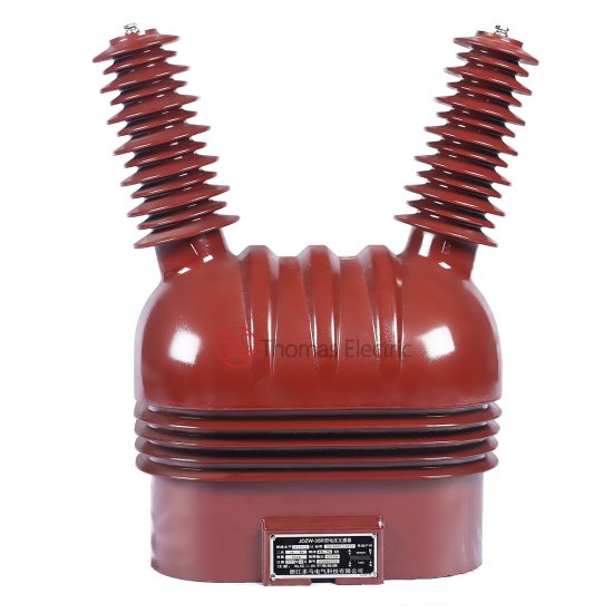
Introduction to the JDZW-35K Voltage Transformer
The JDZW-35K is a single-phase, outdoor-rated cast-resin voltage transformer (VT) designed for accurate voltage measurement and reliable protective relay operation in medium-voltage distribution systems operating at 11kV (IEC standard) or 10kV (domestic Chinese system). As a critical component in secondary circuits of substations, it provides galvanically isolated, scaled-down replicas of primary voltages for metering, monitoring, and protection functions.
Operating Principle of Cast-Resin Insulation
Cast-resin insulation in the JDZW-35K employs vacuum pressure impregnation (VPI) of cycloaliphatic epoxy resin around the high-voltage (HV) and low-voltage (LV) windings wound on grain-oriented electrical steel (GOES) cores. This process eliminates air voids and moisture ingress pathways, resulting in superior dielectric strength and partial discharge performance (<5 pC at 1.2 × Um/√3). The solid dielectric structure ensures stable capacitance and inductance characteristics over the transformer’s operational life, minimizing ratio and phase angle errors under varying load and temperature conditions. Unlike oil-filled units, the absence of liquid insulation eliminates fire hazards, environmental contamination risks, and maintenance-intensive oil sampling procedures.
Advantages Over Oil-Immersed Designs
Compared to traditional oil-immersed VTs, the JDZW-35K offers significant operational and safety benefits. Its dry-type construction enables direct indoor or outdoor mounting without containment bunds, reducing footprint and civil works costs. The epoxy resin matrix exhibits excellent tracking resistance (CTI > 600 V), UV stability, and mechanical robustness against seismic loads (up to 0.5g). Thermal performance is enhanced through optimized heat dissipation via the ribbed housing design, supporting continuous operation at ambient temperatures from -40°C to +40°C. Furthermore, the absence of oil simplifies transportation logistics and eliminates regulatory compliance burdens associated with hazardous material handling.
Typical Applications Overview
The JDZW-35K is predominantly deployed in 11kV/10kV utility substations, industrial switchgear, and renewable energy interconnection points. It serves dual roles: supplying precise voltage signals to revenue-class kWh meters (accuracy class 0.2 or 0.5) and providing fault-detection inputs to overvoltage, undervoltage, and directional earth-fault relays. Its compact dimensions (typically 380 mm height × 220 mm base) facilitate retrofitting into existing bays originally designed for oil-filled units. The transformer’s high short-circuit withstand capability (rated thermal short-time current of 100 A for 1 s) ensures survival during downstream faults without degradation of metrological performance.
Technical Specifications
The JDZW-35K adheres to stringent electrical and environmental parameters defined by IEC 61869-3 and GB/T 20840.3, ensuring interoperability across global power systems.
Rated Electrical Parameters
Primary rated voltage: 11 kV (Um = 12 kV); secondary rated voltage: 100/√3 V or 100 V (configurable). Standard voltage ratios include 11000/100/√3 V and 11000/100 V. Accuracy classes are available in 0.2, 0.5, 1, and 3P for metering and protection applications respectively. Rated outputs range from 10 VA to 100 VA per secondary winding, with thermal limiting output up to 300 VA. Insulation level complies with IEC 60071: LI 75 kV / AC 28 kV (1 min). Burden compatibility follows IEC 61869-3 Annex B, supporting resistive-inductive loads with power factors between 0.8 lagging and unity.
Core and Winding Construction
The magnetic core utilizes 0.23 mm thick GOES (M4 grade) laminations, annealed to minimize hysteresis losses (<0.8 W/kg at 1.7 T, 50 Hz). Primary windings consist of enameled copper wire with Class F (155°C) insulation, while secondary windings use double-insulated stranded copper conductors. Both windings are fully encapsulated in flame-retardant (UL94 V-0) cycloaliphatic epoxy resin under vacuum, achieving a partial discharge inception voltage >1.8 × Um/√3. The design incorporates electrostatic shields between HV and LV windings to suppress capacitive coupling and ensure linearity under transient overvoltages.
Environmental and Mechanical Ratings
Designed for outdoor service (IP54 rating), the JDZW-35K operates reliably at altitudes ≤1000 m (derating factor 1% per 100 m above 1000 m up to 3000 m). Ambient temperature range: -40°C to +40°C; relative humidity: ≤95% non-condensing. Pollution degree: III (creepage distance ≥25 mm/kV). Seismic withstand: horizontal acceleration 0.5g, vertical 0.25g (per IEC 60068-2-57). Mounting is via M16 threaded studs on a standardized 200×200 mm base pattern compatible with IEC 61869-3 dimensional requirements.
Typical Applications
The JDZW-35K’s versatility makes it suitable for diverse power infrastructure scenarios requiring precise voltage transformation with minimal maintenance.
Substation Secondary Metering Systems
In 11kV distribution substations, the JDZW-35K supplies voltage inputs to three-phase kWh meters for billing and energy management. Configured in star connection with open delta tertiary windings (where applicable), it enables neutral displacement monitoring for earth-fault detection. With accuracy class 0.2, ratio error remains within ±0.2% and phase displacement ≤10 minutes at 25–100% of rated burden, meeting IEC 62053-22 requirements for Class 0.2S meters. Its low temperature coefficient (<0.02%/°C) ensures consistent performance across seasonal variations.
Industrial Power Distribution Networks
Large manufacturing facilities utilize the JDZW-35K for motor protection relaying and power quality monitoring. In arc furnace or large induction motor circuits, its high saturation margin (core flux density maintained below 1.5 T at 1.5 × Un) prevents waveform distortion during voltage sags. The 3P accuracy class guarantees ratio error ≤±3% and phase error ≤120 minutes under fault conditions (up to 1.9 × Un for 30 s), enabling reliable operation of undervoltage lockout schemes in motor control centers.
Renewable Energy Integration Points
At solar PV or wind farm grid interconnection points, the JDZW-35K provides synchronization voltage to anti-islanding relays and SCADA RTUs. Its fast response time (<20 ms to 90% of final value during step changes) supports rapid islanding detection per IEEE 1547. The cast-resin construction resists salt fog and dust accumulation common in coastal or desert installations, maintaining insulation integrity without periodic cleaning.
Rural and Suburban Distribution Feeders
In remote areas with limited maintenance access, the JDZW-35K’s maintenance-free design reduces lifecycle costs. Mounted on pole-top platforms or pad-mounted switchgear, it delivers voltage signals to automated feeder sectionalizers and reclosers. The 100 VA output capacity supports multiple parallel burdens (e.g., meter + relay + fault indicator), eliminating the need for auxiliary VTs. Its lightweight (≈45 kg) facilitates helicopter or drone-assisted installation in mountainous terrain.
Harsh Environment Installations
For chemical plants or mining operations with explosive atmospheres, the JDZW-35K’s non-flammable resin meets ATEX Zone 2 requirements when installed with appropriate enclosures. The absence of oil prevents hydrocarbon vapor ignition risks. In cold climates, the resin’s glass transition temperature (>120°C) ensures no embrittlement down to -50°C, validated through IEC 60068-2-1 cold testing.
Compliance with International Standards
Conformance to IEC 61869-3 and GB/T 20840.3 ensures the JDZW-35K meets globally recognized safety, performance, and interoperability benchmarks.
IEC 61869-3 Certification Requirements
IEC 61869-3 defines type tests, routine tests, and special tests for inductive voltage transformers. The JDZW-35K undergoes all mandatory type tests: temperature rise (Δθ ≤60 K for windings), short-circuit withstand (100 A for 1 s without damage), lightning impulse (75 kV peak, 1.2/50 μs), and power frequency wet test (28 kV for 1 min at 10 mm/min rain intensity). Partial discharge measurements confirm <5 pC at 1.2 × 12/√3 kV. Routine tests include ratio verification (±0.2% tolerance for class 0.2), polarity check, and insulation resistance (>1000 MΩ at 2500 V DC).
Alignment with GB/T 20840.3
GB/T 20840.3 harmonizes with IEC 61869-3 but includes China-specific requirements: altitude derating curves up to 4000 m, extended thermal short-time current duration (3 s for some variants), and mandatory seismic testing per GB/T 13540. The JDZW-35K’s domestic 10kV rating (vs. IEC 11kV) reflects China’s nominal system voltage, though insulation levels remain identical (Um=12 kV). Accuracy class definitions and burden tables align precisely with IEC, ensuring seamless export compatibility.
Key Differences Between IEC and Domestic Standards
While IEC 61869-3 permits optional residual voltage windings, GB/T 20840.3 mandates them for all 10kV VTs used in earth-fault protection. Consequently, many JDZW-35K units feature a tertiary (a,n) winding rated 100/3 V for zero-sequence voltage measurement. Additionally, Chinese utilities often specify higher thermal outputs (e.g., 150 VA) than typical IEC applications, necessitating reinforced secondary terminals. However, core loss limits (≤1.5 W at 1.1 × Un) and magnetizing current thresholds (<0.5% of rated current) are consistent across both standards.
On-Site Testing Procedures
Field commissioning and periodic verification require standardized tests to validate performance and safety.
Insulation Resistance Test
Using a 2500 V DC megohmmeter, measure insulation resistance between HV-LV, HV-ground, and LV-ground. Acceptance criteria: >1000 MΩ at 20°C. Correct for temperature using RT2 = RT1 × 2(T1-T2)/10. Values below 500 MΩ indicate moisture ingress or resin cracking, requiring drying or replacement. Perform before and after dielectric tests to detect insulation degradation.
Turns Ratio Verification
Apply 100–200 V AC to the primary and measure secondary voltage with a calibrated voltmeter (accuracy class 0.1). Calculate ratio as Vp/Vs. Tolerance: ±0.2% for class 0.2, ±0.5% for class 0.5. Deviations beyond tolerance suggest turn-to-turn shorts or incorrect tap selection. Use a dedicated ratio tester (e.g., Omicron CT Analyzer) for automated comparison against nameplate values.
Polarity Confirmation
Verify reducing polarity using the DC kick method: connect a 6–12 V battery momentarily between HV terminals (H1-H2). Observe secondary voltage polarity with an analog voltmeter; momentary positive deflection at X1-X2 confirms correct polarity. Incorrect polarity causes 180° phase reversal, leading to metering errors or relay misoperation. Document results with oscillograph traces if available.
Power Frequency Withstand Test
Apply 28 kV RMS (50 Hz) between HV and grounded LV/enclosure for 1 minute. Monitor for flashover, excessive leakage current (>1 mA), or audible discharge. Reduce voltage gradually post-test. This validates insulation integrity after transport or prolonged storage. Never perform if ambient humidity exceeds 80% or surface is contaminated.
Open-Circuit Characteristic Test
With secondary open, apply 0–120% of rated primary voltage in 10% increments. Record excitation current and secondary voltage. Plot Vs vs. Imag; knee point should exceed 1.5 × Un. Excessive magnetizing current (>1% of rated) indicates core saturation or shorted turns. Compare with factory curves—deviations >10% warrant further investigation.
Preventive Maintenance Guide
Proactive maintenance extends service life and prevents unexpected failures.
Annual Visual and Functional Inspection
Inspect for resin cracks, tracking marks, or terminal corrosion. Clean housing with mild detergent; avoid solvents that degrade epoxy. Verify torque on M10 secondary terminals (25 N·m) and M16 mounting bolts (80 N·m). Check grounding continuity (<0.1 Ω resistance). Perform insulation resistance and ratio tests annually in critical applications (e.g., hospital backup systems).
Five-Year Comprehensive Maintenance
Every 60 months, conduct full suite of commissioning tests plus partial discharge measurement (if portable PD detector available). Acceptable PD level: <10 pC at 1.2 × Um/√3. Replace silica gel breathers if present (though most JDZW-35K units are fully sealed). Review historical test data for trends—e.g., rising excitation current may precede core lamination failure.
Maintenance Intervals and Fault Diagnosis
| Interval | Tasks | Fault Indicators |
|---|---|---|
| Annually | Visual inspection, IR test, ratio check | Cracks, IR <500 MΩ, ratio error >0.5% |
| 5 Years | Full dielectric tests, PD measurement | PD >15 pC, withstand test failure |
| After Fault | Post-fault ratio and IR tests | Sudden ratio shift, burnt odor |
Common faults include moisture-induced insulation breakdown (evidenced by white powder on terminals) and secondary winding opens (causing infinite ratio). Neither is field-repairable—replace unit immediately.
Conclusion
The JDZW-35K 11kV cast-resin voltage transformer represents a mature, standards-compliant solution for modern medium-voltage infrastructure. Its VPI epoxy resin encapsulation delivers exceptional dielectric reliability, eliminating the fire and environmental risks inherent in oil-filled alternatives. With precision-engineered GOES cores and rigorous adherence to IEC 61869-3 and GB/T 20840.3, it ensures metrological accuracy for revenue metering while providing robust fault signaling for protection systems. The transformer’s maintenance-free design, coupled with a service life exceeding 25–30 years under normal conditions, significantly reduces total cost of ownership. Its compatibility with both international (11kV) and domestic Chinese (10kV) networks enhances deployment flexibility across global markets. For engineers specifying instrumentation in new substations or upgrading legacy systems, the JDZW-35K offers a technically sound, future-proof choice that balances performance, safety, and lifecycle economics. Regular adherence to the outlined testing and maintenance protocols will maximize operational reliability and extend asset longevity well beyond industry averages.
Frequently Asked Questions (FAQ)
Q1: Can the JDZW-35K be used on a 10kV system even though it’s rated 11kV?
A1: Yes. The 11kV rating refers to the IEC standard highest voltage for equipment (Um=12kV), which covers 10kV domestic systems (Um=12kV). The insulation level (LI 75 kV / AC 28 kV) is identical for both, making it fully compatible.
Q2: What is the maximum allowable burden for a class 0.2 JDZW-35K?
A2: The rated output defines the maximum burden at specified accuracy. For example, a 30 VA class 0.2 unit must not exceed 30 VA total burden (including wiring resistance). Exceeding this increases ratio error beyond ±0.2%.
Q3: How often should partial discharge testing be performed?
A3: PD testing is typically a type test but recommended every 5 years in critical applications or after severe overvoltage events. Field-measured values should remain below 10 pC at 1.2 × Um/√3.
Q4: Is the JDZW-35K suitable for indoor installation?
A4: Yes, despite its outdoor (IP54) rating, it can be installed indoors. Ensure ambient temperature does not exceed +40°C and provide adequate clearance (≥150 mm) for convection cooling.
Q5: What causes ratio drift over time?
A5: Primary causes include core lamination degradation due to mechanical stress, moisture ingress compromising insulation, or thermal aging of windings. Annual ratio tests detect drift early—investigate if error exceeds 50% of class tolerance.
Q6: Can multiple secondary windings be connected in parallel?
A6: Only if they are identical in ratio and polarity. Parallel connection doubles the burden capacity but requires matched impedance to prevent circulating currents. Verify with open-circuit voltage balance before paralleling.