Article Content
Introduction to the JLS-35K Current Transformer
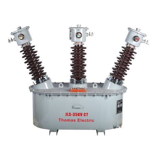
The JLS-35K is a high-voltage, outdoor-rated cast-resin current transformer (CT) engineered for reliable operation in 33kV (IEC) / 35kV (domestic) power systems. Designed in strict accordance with IEC 61869-2 and GB/T 20840.2, this instrument transformer delivers precise current measurement for both metering and protective relaying applications in transmission and distribution substations. Its robust construction leverages vacuum pressure impregnation (VPI) epoxy resin technology to encapsulate the magnetic core and windings, eliminating risks associated with oil-filled alternatives such as leakage, fire hazard, or environmental contamination.
Operating Principle of Cast-Resin Insulation
Cast-resin insulation in the JLS-35K employs a two-stage VPI process where the wound core assembly is first evacuated to remove air and moisture, then impregnated under pressure with cycloaliphatic epoxy resin. This creates a monolithic, void-free solid dielectric barrier with excellent tracking resistance and hydrophobic surface properties. The resin system provides uniform electric field distribution, suppresses partial discharges (<5 pC at 1.2 × Um/√3), and maintains mechanical integrity across thermal cycles from -40°C to +40°C ambient. Unlike oil-paper insulation, cast-resin does not degrade over time due to oxidation or moisture ingress, ensuring long-term dielectric stability without maintenance.
Advantages Over Oil-Immersed Designs
The JLS-35K eliminates the operational liabilities of traditional oil-immersed CTs. There is no risk of oil leakage during transport, installation, or service—critical for urban substations near sensitive infrastructure. Fire safety is inherently enhanced, as epoxy resin is self-extinguishing (UL 94 V-0 rated). The unit requires no oil sampling, degassing, or topping-up, reducing lifecycle costs by up to 40% over 30 years. Additionally, the compact footprint (typically 30% smaller than equivalent oil units) simplifies retrofitting in space-constrained switchyards. Environmental compliance is assured, as the design contains no PCBs or hazardous fluids, aligning with RoHS and WEEE directives.
Typical Applications Overview
This CT is deployed primarily in outdoor 33kV/35kV air-insulated substations (AIS) for revenue metering, fault detection, and feeder protection. It interfaces directly with primary conductors carrying up to 2000 A continuous current and supports multiple secondary windings (e.g., 0.2S for metering, 5P20 for protection). Common installations include ring main units (RMUs), generator step-up transformers, and grid interconnection points for solar/wind farms. Its pollution degree III rating (per IEC 60664-1) ensures reliable performance in coastal, industrial, or desert environments with high salinity or dust loading.
Technical Specifications
The JLS-35K adheres to stringent electrical and mechanical parameters defined by international standards. Below is a representative specification table for a typical dual-winding configuration:
| Parameter | Value |
|---|---|
| Rated System Voltage (IEC) | 33 kV |
| Maximum System Voltage (Um) | 36 kV |
| Domestic System Voltage | 35 kV |
| Primary Current Ratings | 50–2000 A (standard steps) |
| Secondary Current | 1 A or 5 A |
| Accuracy Classes | Metering: 0.2S, 0.5S; Protection: 5P10, 5P20 |
| Rated Burden (per winding) | 5–30 VA (at cos φ = 0.8 lag) |
| Short-Time Thermal Current | 25 kA for 1 s (Ith) |
| Dynamic Withstand Current | 62.5 kA peak (Idyn) |
| Power Frequency Withstand Voltage | 70 kV rms, 1 min (phase-to-earth) |
| Lightning Impulse Withstand | 170 kV peak (1.2/50 μs) |
| Insulation Material | VPI cycloaliphatic epoxy resin |
| Magnetic Core | Grain-oriented electrical steel (GOES), low-loss grade |
| Ambient Temperature Range | -40°C to +40°C |
| Altitude Limit | ≤1000 m (derating required above) |
| Pollution Degree | III (creepage distance ≥25 mm/kV) |
Standard Service Conditions
The JLS-35K is rated for continuous operation under IEC 60071-1 standard atmospheric conditions: ambient temperature between -40°C and +40°C, relative humidity up to 100% (condensation permitted), and installation altitude not exceeding 1000 meters above sea level. At higher altitudes (up to 3000 m), voltage withstand capabilities must be derated per IEC 60071-2—typically by 1% per 100 m above 1000 m. The unit is designed for vertical or horizontal mounting with primary conductor orientation parallel to the ground plane. Solar radiation exposure is accounted for in thermal design, with surface temperature rise limited to ≤55 K above ambient under full load.
Core and Winding Design
The magnetic circuit utilizes grain-oriented electrical steel (GOES) laminations with a maximum specific loss of 1.0 W/kg at 1.7 T and 50 Hz. This minimizes no-load losses and enhances accuracy under low-current conditions—critical for 0.2S class metering. Secondary windings are bifilar-wound with enameled copper wire (Class F insulation, 155°C rating) and embedded within the resin matrix to prevent movement during short-circuit events. Each winding is individually shielded to reduce capacitive coupling and ensure immunity to electromagnetic interference (EMI) from adjacent phases or HV busbars.
Typical Applications
The JLS-35K serves diverse roles across modern power infrastructure, leveraging its dual-winding capability and high accuracy to support both commercial metering and system protection functions.
Substation Secondary Metering
In utility-owned 33kV/35kV substations, the JLS-35K’s 0.2S-class winding provides revenue-grade current signals to kWh meters and SCADA RTUs. For example, a 600/5 A ratio unit feeding a 10 VA burden ensures error within ±0.2% at 100% load and ±0.35% at 20% load—meeting IEC 62053-22 requirements for billing accuracy. The cast-resin housing resists UV degradation and thermal cycling, maintaining calibration stability over decades without recalibration. This is essential for regulatory compliance in deregulated markets where metering disputes can incur significant financial penalties.
Industrial Power Distribution
Large manufacturing plants often operate private 35kV networks fed from utility tie-lines. Here, the JLS-35K monitors energy consumption for cost allocation and detects internal faults via 5P20 protection windings. In a steel mill application, the CT withstands harmonic distortion from arc furnaces (THD up to 15%) without saturation, thanks to its high knee-point voltage (>150 V at 5 A secondary). The unit’s IP54-rated terminal box protects secondary connections from metal dust and coolant splashes, ensuring signal integrity to digital relays like SEL-751 or Siemens 7SJ62.
Renewable Energy Integration
Solar photovoltaic (PV) and wind farms frequently connect to the grid via 33kV collector systems. The JLS-35K enables precise generation metering for feed-in tariffs and provides fault current data for anti-islanding protection. During cloud-induced ramp events in PV plants, the CT accurately tracks rapid current changes (di/dt > 100 A/ms) without phase shift error exceeding 10 minutes—critical for synchrophasor applications. Its outdoor design tolerates wide diurnal temperature swings (e.g., -20°C night to +50°C day in desert installations) without cracking or delamination.
Rural and Suburban Distribution Networks
In remote areas with limited maintenance access, the JLS-35K’s maintenance-free operation is invaluable. Deployed on pole-mounted reclosers or pad-mounted switchgear, it supports automated sectionalizing schemes using 5P10 windings. For instance, a 400/1 A unit with 10 VA burden drives a microprocessor-based recloser that trips within 3 cycles for downstream faults. The high creepage distance (≥880 mm for 33kV) prevents flashovers during fog or light rain, reducing outages in humid climates like Southeast Asia or South America.
Compliance with International Standards
The JLS-35K is certified to both global and Chinese national standards, ensuring interoperability and regulatory acceptance across markets.
IEC 61869-2 Compliance Details
IEC 61869-2 specifies performance, testing, and marking requirements for standalone current transformers. The JLS-35K meets all mandatory clauses, including:
– Accuracy verification per Annex A (ratio error and phase displacement limits)
– Thermal and dynamic short-circuit withstand tests (Clause 6.5)
– Partial discharge measurement (<10 pC at 1.2 × Um/√3)
- Temperature rise test (winding ≤60 K, terminals ≤50 K)
- Marking requirements (rated voltage, ratio, accuracy class, burden, polarity)
Each unit undergoes type testing at an accredited laboratory, with results documented in a test report traceable to ISO/IEC 17025.
GB/T 20840.2 Alignment
China’s GB/T 20840.2 mirrors IEC 61869-2 but includes additional requirements for domestic grids:
– Higher lightning impulse level (185 kV vs. IEC’s 170 kV for 35kV class)
– Mandatory seismic qualification (0.3g horizontal acceleration)
– Stricter pollution performance (creepage ≥31 mm/kV for heavy industrial zones)
The JLS-35K exceeds these criteria, featuring reinforced flange bolts for seismic resilience and extended sheds for enhanced pollution flashover margin. This dual compliance allows seamless deployment in projects funded by Chinese EPC contractors operating internationally.
Key Differences Between IEC and Domestic Standards
While IEC 61869-2 focuses on functional performance, GB/T 20840.2 emphasizes environmental robustness. For example, GB requires salt fog testing per IEC 60068-2-11 (96 hours, 5% NaCl solution), whereas IEC references it only as optional. Similarly, GB mandates a 10,000-cycle mechanical endurance test on primary terminals, simulating thermal expansion stresses absent in IEC. The JLS-35K incorporates thicker terminal lugs (M16 stainless steel) and silicone rubber gaskets to satisfy both regimes without redesign.
On-Site Testing Procedures
Field commissioning of the JLS-35K requires verification of insulation integrity, transformation accuracy, and polarity before energization.
Insulation Resistance Test
Using a 5 kV DC megohmmeter, measure insulation resistance between primary winding and earthed housing, and between secondary windings and earth. Acceptance criterion: ≥10,000 MΩ at 20°C. Correct for temperature using Rt = R20 × 2(20−t)/10. Values below 5,000 MΩ indicate moisture ingress or resin cracking and require drying or replacement. Perform this test after transportation or prolonged storage in humid conditions.
Turns Ratio Test
Apply a low-voltage AC source (5–10 V) to the primary and measure secondary voltage. Calculate actual ratio = Vpri/Vsec. Compare to nameplate ratio; tolerance must be within ±0.25% for metering windings and ±1% for protection windings per IEC 61869-2 Table 102. Use a precision ratio bridge (e.g., Omicron CT Analyzer) for 0.2S-class verification. Deviations beyond tolerance suggest turn-to-turn shorts or incorrect tap selection.
Polarity Test
Verify reducing polarity using the DC kick method: momentarily connect a 6 V battery across primary terminals (P1 to +, P2 to −). Observe secondary voltage polarity with a DC voltmeter—positive deflection at S1 confirms correct polarity. Incorrect polarity causes relay misoperation; e.g., a differential relay may trip during external faults. Always recheck polarity after secondary wiring modifications.
Power Frequency Withstand Voltage Test
Apply 70 kV rms (50 Hz) between primary and grounded housing for 1 minute. Monitor for flashover, excessive leakage current (>1 mA), or audible discharge. This test validates dielectric strength after handling damage. Reduce voltage to 80% (56 kV) if performed post-installation with adjacent live equipment. Never exceed 1-minute duration to avoid resin aging.
Short-Circuit Test (for CT)
Unlike VTs, CTs require verification of saturation characteristics. Inject 10× rated secondary current (e.g., 50 A for 5 A CT) into the secondary while monitoring primary voltage. Knee-point voltage must exceed specified value (e.g., >150 V). Alternatively, use excitation curve testing per IEEE C57.13.1: plot volts vs. amps on secondary; abrupt slope change indicates saturation. Ensure protection windings saturate above 20× rated current (5P20) to maintain accuracy during faults.
Preventive Maintenance Guide
Although cast-resin CTs are largely maintenance-free, periodic checks ensure decades of reliable service.
Annual Visual and Functional Inspection
Inspect for:
– Surface cracks, tracking, or UV discoloration on resin housing
– Corrosion on primary terminals or mounting hardware
– Loose secondary connections in terminal box (torque to 2.5 N·m)
– Moisture ingress (fogging inside sight glass, if equipped)
Perform insulation resistance and ratio tests annually in critical applications (e.g., revenue metering). Clean housing with non-abrasive detergent if salt or dust deposits exceed 1 mm thickness—use deionized water rinse to avoid mineral residue.
Five-Year Comprehensive Maintenance
At five-year intervals, conduct:
– Full IEC 61869-2 routine tests (ratio, polarity, insulation)
– Partial discharge measurement (<10 pC at 1.2 × Um/√3)
- Terminal contact resistance check (<100 μΩ per joint)
- Verification of grounding continuity (<0.1 Ω to substation grid)
Replace terminal box gaskets if hardened or cracked. Record all test data in asset management software to trend degradation—e.g., rising excitation current may indicate core fatigue.
Maintenance Intervals and Fault Diagnosis
| Interval | Task | Fault Indicator |
|---|---|---|
| Annually | Visual inspection, IR scan | Hot spot >10 K above ambient |
| Every 3 years | Ratio & polarity test | Ratio error >1% |
| Every 5 years | Full dielectric tests | PD >15 pC, IR <5 GΩ |
| After fault | Dynamic withstand check | Visible deformation, noise |
Common failure modes include secondary open-circuit (causing core saturation and overheating) and terminal corrosion (increasing contact resistance). Never operate with secondary open—always short-circuit terminals during removal.
Conclusion
The JLS-35K 33kV cast-resin current transformer represents a benchmark in reliability, accuracy, and compliance for medium-voltage power systems. By integrating advanced VPI epoxy resin technology with GOES magnetic cores, it delivers exceptional performance across metering and protection applications while eliminating the environmental and safety concerns of oil-filled alternatives. Its dual certification to IEC 61869-2 and GB/T 20840.2 ensures global acceptance, from European transmission grids to Chinese renewable energy projects. Rigorous factory testing and straightforward field verification procedures guarantee consistent operation under harsh environmental conditions, including high pollution, extreme temperatures, and seismic activity. With a design life exceeding 30 years and minimal maintenance requirements, the JLS-35K offers a compelling total cost of ownership advantage. Utilities and industrial operators can confidently deploy this CT in critical infrastructure, knowing it will maintain calibration stability, withstand fault currents, and support grid modernization initiatives for decades.
Frequently Asked Questions (FAQ)
Q1: Can the JLS-35K be used on a 35kV domestic system even though it’s rated 33kV IEC?
Yes. The 33kV IEC rating corresponds to a maximum system voltage (Um) of 36kV, which fully covers the 35kV nominal domestic system (Um = 40.5kV in some regions). Always verify local grid codes, but the JLS-35K’s 70kV power frequency withstand exceeds requirements for both standards.
Q2: What is the minimum secondary burden for accurate 0.2S operation?
Per IEC 61869-2, the burden must be ≥25% of rated burden (e.g., ≥2.5 VA for a 10 VA winding). Operating below this increases ratio error beyond class limits. Use burden resistors if connected to high-impedance digital meters.
Q3: How do I test polarity if the primary is busbar-mounted and inaccessible?
Use the secondary injection method: apply known current to secondary and measure induced voltage on primary with a high-impedance voltmeter. Polarity is confirmed if P1 voltage leads S1 by 180°. Alternatively, use a portable CT analyzer with auto-polarity detection.
Q4: Is cleaning the resin housing necessary, and how often?
In pollution class III environments (coastal/industrial), clean every 2–3 years using soft brush and mild detergent. Avoid solvents that degrade epoxy. Inspect during annual IR scans—if surface conductivity exceeds 100 μS, cleaning is urgent to prevent flashover.
Q5: Can I parallel two secondary windings for higher burden capacity?
No. Paralleling windings alters the effective turns ratio and may cause circulating currents. Instead, select a single winding with adequate VA rating or use separate windings for distinct loads (e.g., one for metering, one for protection).
Q6: What causes a sudden increase in excitation current during testing?
This typically indicates core damage from mechanical shock (e.g., during transport) or thermal degradation due to repeated secondary open-circuit events. If excitation current doubles from baseline, replace the CT—continued operation risks insulation failure.