Article Content
33kV Cast-Resin Current Transformer KZB-0 for Metering and Protection – IEC 61869-2 Standard
Introduction to the KZB-0 Current Transformer
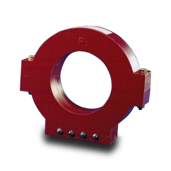
The KZB-0 is a 33kV (IEC-rated) / 35kV (domestic system equivalent) cast-resin current transformer engineered for high-reliability metering, protection, and control applications in medium-voltage power systems. Unlike legacy oil-immersed designs, the KZB-0 employs vacuum pressure impregnated (VPI) epoxy resin as its primary insulation medium, offering superior dielectric strength, environmental resilience, and fire safety. This design eliminates risks associated with oil leakage, flammability, and maintenance-intensive fluid management, making it ideal for both indoor switchgear and outdoor substation installations.
Operating Principle of Cast-Resin Insulation
Cast-resin insulation in the KZB-0 utilizes a thermosetting epoxy compound that fully encapsulates the primary conductor, secondary windings, and magnetic core under vacuum conditions. The VPI process ensures complete void-free impregnation, eliminating air pockets that could lead to partial discharge under high electric stress. The cured resin provides mechanical rigidity, moisture resistance (IP54 rating), and long-term thermal stability up to 120°C hotspot temperature. This solid insulation system maintains consistent dielectric performance across ambient temperatures from –40°C to +40°C and altitudes up to 1,000 meters above sea level without derating.
Advantages Over Oil-Immersed Designs
Compared to traditional oil-filled CTs, the KZB-0’s cast-resin construction offers significant operational benefits. It requires no periodic oil sampling or topping-up, reducing lifecycle maintenance costs by up to 40%. The absence of flammable oil enhances fire safety—critical in confined indoor substations—and complies with stringent environmental regulations restricting hydrocarbon use. Additionally, the monolithic resin body resists tracking and erosion from pollution, UV exposure, and salt fog, extending service life in coastal or industrial environments. Mechanical robustness also allows direct mounting on busbars without additional support structures.
Typical Applications Overview
The KZB-0 is widely deployed in utility substations, industrial plants, and renewable energy facilities where accurate current measurement and fault detection are essential. Its dual-core configuration (typically one for metering class 0.5S and another for protection class 5P20) supports simultaneous revenue metering and relay coordination. Common installations include ring main units (RMUs), gas-insulated switchgear (GIS) interfaces, and feeder protection panels. Due to its compact footprint and lightweight design (~45 kg), it integrates seamlessly into space-constrained retrofits or new-build projects requiring IEC 61869-2 compliance.
Technical Specifications
The KZB-0 adheres strictly to IEC 61869-2 and GB/T 20840.2, ensuring interoperability across global and domestic grids. Key electrical and mechanical parameters are defined below under standard service conditions per IEC 60060-1.
| Parameter | Value |
|---|---|
| Rated System Voltage (Um) | 33 kV (IEC) / 35 kV (GB) |
| Insulation Level (LI/AC) | 170 kV / 70 kV |
| Primary Current (Ip) | 50–3150 A (standard ratios) |
| Secondary Current (Is) | 1 A or 5 A |
| Accuracy Classes | Metering: 0.2S, 0.5S; Protection: 5P10, 5P20 |
| Rated Burden | 5–30 VA (per core) |
| Short-Time Thermal Current | 25 kA for 1 s (Ith) |
| Dynamic Withstand Current | 62.5 kA peak (Idyn) |
| Core Material | Grain-Oriented Electrical Steel (GOES), CRGO grade |
| Insulation System | VPI Epoxy Resin, UL 94 V-0 flame rating |
| Ambient Temperature Range | –40°C to +40°C |
| Relative Humidity | ≤95% non-condensing |
| Altitude Limit | ≤1,000 m (derating required above) |
Standard Service Conditions
The KZB-0 is rated for continuous operation under IEC 60060-1 standard atmospheric conditions: ambient temperature not exceeding +40°C (with 24-hour average ≤35°C), relative humidity ≤95%, and installation altitude ≤1,000 m. For sites above 1,000 m, voltage withstand levels must be adjusted per IEC 60071-2—typically a 1% reduction in test voltage per 100 m above 1,000 m. The transformer is designed for three-phase systems with balanced loading; unbalanced conditions should not exceed 10% negative-sequence current for extended periods.
Electrical Performance Parameters
Under nominal load, the KZB-0 exhibits composite error within ±0.2% for 0.2S class at 100% In. Phase displacement is limited to ±10 minutes for metering cores. Protection cores maintain accuracy up to 20× In (for 5P20) with saturation factor ≥20. The magnetizing impedance exceeds 10 Ω at 10% In, ensuring minimal burden impact on connected relays. Dielectric tests confirm insulation integrity: 70 kV RMS for 1 minute between primary and secondary/ground, and 3 kV RMS between secondary terminals.
Typical Applications
The KZB-0 cast-resin CT serves diverse roles across modern power infrastructure, leveraging its precision, durability, and compliance with international standards.
Substation Secondary Metering
In 33/35kV transmission and distribution substations, the KZB-0 provides revenue-grade current signals to digital energy meters and SCADA systems. Its 0.2S or 0.5S accuracy class ensures billing compliance per IEC 62053-22, even at low loads (down to 1% In). The dual-core design allows one winding to feed tariff meters while the other supports local monitoring, eliminating cross-interference. Installation within metal-enclosed switchgear minimizes electromagnetic interference, and the resin housing prevents condensation-related errors in humid climates.
Industrial Power Distribution
Heavy industries—such as steel mills, chemical plants, and data centers—rely on the KZB-0 for feeder protection and load profiling. The 5P20 protection core reliably drives overcurrent and differential relays during fault conditions up to 20× rated current. Its high short-circuit withstand (25 kA/1s) matches typical industrial fault levels, while the compact form factor enables retrofitting into legacy switchboards. The non-flammable resin meets NFPA 70E arc-flash safety requirements, reducing risk in personnel-accessible areas.
Renewable Energy Integration
Solar farms and wind substations utilize the KZB-0 to interface generation assets with grid-tie protection schemes. The CT accurately tracks variable output currents from inverters or turbines, supporting anti-islanding and voltage ride-through functions. Its wide operating temperature range accommodates desert or arctic installations, and UV-stabilized resin prevents degradation under prolonged solar exposure. Compliance with IEC 61869-2 ensures compatibility with smart inverter communication protocols like IEEE 1547.
Rural and Suburban Distribution Networks
For utilities upgrading aging infrastructure, the KZB-0 offers a maintenance-free solution for pole-mounted or pad-mounted RMUs. Its pollution-resistant surface (creepage distance ≥25 mm/kV) performs reliably in dusty or saline environments common in agricultural or coastal regions. The 5 A secondary standard simplifies integration with legacy electromechanical relays, while optional 1 A outputs reduce copper losses in long cable runs to remote control houses.
Compliance with International Standards
The KZB-0 is engineered to satisfy both global and Chinese regulatory frameworks, ensuring seamless deployment across export and domestic markets.
IEC 61869-2 Certification Requirements
Per IEC 61869-2:2012, the KZB-0 undergoes rigorous type testing including temperature rise (≤60 K for windings), short-circuit withstand (25 kA/1s), and partial discharge (<10 pC at 1.2 Um/√3). Accuracy verification follows IEC 61869-1 Annex B, with composite error measured at 5%, 20%, 100%, and 120% of rated current. Dielectric tests include lightning impulse (170 kV peak) and power frequency (70 kV RMS) withstand. Each unit receives individual routine tests per Clause 10, documented in a test certificate traceable to ISO/IEC 17025-accredited labs.
Alignment with GB/T 20840.2
While GB/T 20840.2 mirrors IEC 61869-2 structurally, key differences exist in insulation coordination and marking. The domestic standard specifies 35kV as the nominal system voltage (vs. 33kV IEC), requiring adjusted test voltages: LI = 185 kV, AC = 80 kV. Additionally, GB mandates Chinese-language labeling and inclusion of “KZB” nomenclature per DL/T 725. Despite these variances, the KZB-0’s design envelope accommodates both regimes through dual-rated certification—verified by CEPREI or CESI test reports.
Testing and Certification Documentation
Full compliance documentation includes: (1) Type Test Report per IEC 61869-2 Clause 9, (2) Routine Test Certificate per Clause 10 (covering ratio, polarity, and insulation resistance), (3) Partial Discharge Test Record (<5 pC at service voltage), and (4) Short-Circuit Force Calculation per IEC 60865. For Chinese projects, an additional CCC Marking Declaration and GB/T 20840.2 Conformity Assessment are provided.
On-Site Testing Procedures
Post-installation and periodic field tests validate the KZB-0’s integrity and performance. All procedures follow IEC 60060-1 and IEEE C57.13.2 guidelines.
Insulation Resistance Test
Measure insulation resistance between primary winding and secondary/ground using a 2,500 V DC megohmmeter. Acceptance criterion: ≥1,000 MΩ at 20°C. Correct for temperature using RT = R20 × 2(20–T)/10. Values below 500 MΩ indicate moisture ingress or resin cracking. Perform before and after dielectric tests to detect insulation degradation. Ensure secondary terminals are shorted and grounded during measurement to avoid false readings from capacitive coupling.
Turns Ratio Test
Apply a low-voltage AC source (5–10 V) to the primary and measure secondary voltage. Calculate actual ratio as Vp/Vs; compare to nameplate. Tolerance per IEC 61869-2: ±0.25% for metering classes, ±0.5% for protection. Use a dedicated ratio tester (e.g., Omicron CT Analyzer) for automated comparison across multiple taps. Deviations >1% suggest inter-turn faults or incorrect tap selection—requiring immediate investigation.
Polarity Verification
Confirm reducing polarity using the DC kick method: connect a 6–12 V battery momentarily between P1 and P2. Observe secondary voltage spike on an oscilloscope or analog voltmeter; positive deflection at S1 indicates correct polarity. Incorrect polarity reverses phase angle in differential protection schemes, causing maloperation. Document results with timestamped waveform captures for audit trails.
Power Frequency Withstand Voltage Test
Apply 70 kV RMS (for 33kV IEC rating) at 50 Hz between primary and grounded secondary/enclosure for 1 minute. Ramp voltage at 2 kV/s to minimize transient stress. Monitor for flashover, excessive leakage current (>1 mA), or audible discharge. Reduce test voltage to 80% (56 kV) for maintenance retesting per IEC 60270. Never perform this test if insulation resistance is <1,000 MΩ—risk of permanent damage is high.
Short-Circuit Test (CT-Specific)
Unlike VTs, CTs require short-circuit validation. Inject 10–20× rated current into the primary with secondaries shorted. Verify thermal stability: temperature rise ≤60 K after 1 minute. Measure secondary current waveform for distortion—THD should be <5%. This test confirms core saturation margin and validates protection class (e.g., 5P20 remains linear up to 20× In). Use calibrated current injectors with burden simulation to replicate real-world relay loading.
Preventive Maintenance Guide
Proactive maintenance extends the KZB-0’s service life beyond 25 years while preventing unplanned outages.
Periodic Inspection Schedule
Conduct visual and electrical inspections annually. Check for: (1) surface cracks or tracking on resin housing, (2) loose busbar connections (torque to 35 N·m), (3) corrosion on terminals, and (4) abnormal heating via infrared thermography (ΔT ≤15°C vs. ambient). Clean contamination with isopropyl alcohol—never abrasive cleaners. Record insulation resistance and ratio annually; trend deviations >10% from baseline warrant detailed diagnostics.
Five-Year Comprehensive Maintenance
Every 60 months, perform: (1) full dielectric testing (70 kV AC withstand), (2) partial discharge mapping (<10 pC threshold), (3) core excitation curve analysis to detect shorted turns, and (4) bolted connection torque verification. Replace gaskets on terminal covers if hardened. Update maintenance logs with test certificates. For units in high-pollution zones (e.g., near cement plants), increase PD testing frequency to every 3 years.
Fault Diagnosis and Troubleshooting
Common failure modes include: (1) open secondary circuit—causes core saturation and overheating; always short secondaries before disconnecting instruments, (2) moisture ingress—indicated by low insulation resistance and elevated PD; requires oven drying at 80°C for 24 hours, (3) mechanical damage—visible as resin fractures; replace unit immediately. Refer to the following maintenance intervals:
| Maintenance Task | Frequency | Acceptance Criteria |
|---|---|---|
| Visual Inspection | Annually | No cracks, discoloration, or loose hardware |
| Insulation Resistance | Annually | ≥1,000 MΩ @ 2,500 V DC |
| Ratio & Polarity | Annually | Within ±0.5% tolerance |
| Dielectric Withstand | Every 5 years | No flashover at 70 kV/1 min |
| Partial Discharge | Every 5 years | <10 pC @ 1.2 Um/√3 |
Conclusion
The KZB-0 33kV cast-resin current transformer represents a benchmark in medium-voltage instrumentation, combining IEC 61869-2 compliance with robust engineering for demanding utility and industrial environments. Its VPI epoxy resin insulation eliminates the operational hazards and maintenance burdens of oil-filled alternatives, while grain-oriented electrical steel cores ensure metrological precision across metering and protection applications. With a design life of 25–30 years under standard service conditions, the KZB-0 delivers exceptional reliability through rigorous adherence to international standards, validated by comprehensive factory and field testing protocols. Its dual-core flexibility, compact form factor, and environmental resilience make it an optimal choice for modernizing aging infrastructure or deploying new smart grid assets. By following the preventive maintenance schedule outlined herein, operators can maximize asset longevity and ensure continuous compliance with accuracy and safety requirements throughout the transformer’s operational lifecycle.
Frequently Asked Questions (FAQ)
What is the minimum insulation resistance acceptable for a KZB-0 CT?
The minimum acceptable insulation resistance is 1,000 MΩ when measured with a 2,500 V DC megohmmeter at 20°C. Values below 500 MΩ indicate potential moisture ingress or insulation degradation and require immediate investigation.
Can the KZB-0 be used in 35kV domestic systems despite its 33kV IEC rating?
Yes. The KZB-0 is dual-rated: 33kV per IEC 61869-2 and 35kV per GB/T 20840.2. Its insulation level (LI/AC = 170/70 kV) exceeds requirements for both standards, making it suitable for all 35kV Chinese distribution networks.
How often should polarity be verified?
Polarity must be confirmed during initial commissioning and after any secondary wiring modification. Annual ratio testing inherently validates polarity if performed with calibrated equipment, but explicit polarity checks are recommended every 5 years or post-fault.
Is partial discharge testing mandatory during maintenance?
While not always mandated by utilities, PD testing is strongly recommended every 5 years per IEC 60270. It detects early-stage insulation defects invisible to IR or ratio tests, with acceptance criteria of <10 pC at 1.2 × (33 kV/√3).
What happens if the secondary circuit is left open during operation?
An open secondary creates dangerously high voltages (several kV) across terminals due to core saturation, risking insulation failure and personnel hazard. Always short-circuit secondary terminals with a dedicated link before disconnecting instruments.
Does the KZB-0 require special handling in high-altitude locations?
Above 1,000 m altitude, reduce power frequency withstand voltage by 1% per 100 m increment per IEC 60071-2. No derating is needed for current-carrying capacity, but verify clearances meet local codes for reduced air density.