Article Content
Introduction to the UTF-8 Current Transformer
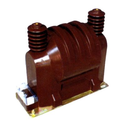
The UTF-8 is a high-reliability, cast-resin insulated current transformer (CT) engineered for accurate current measurement and protective relaying in medium-voltage power systems operating at 11kV (IEC standard) or 10kV (domestic Chinese grid). Designed in strict compliance with IEC 61869-2 and GB/T 20840.2, this instrument transformer leverages advanced vacuum pressure impregnation (VPI) epoxy resin technology to deliver exceptional dielectric strength, environmental resilience, and long-term operational stability.
Operating Principle of Cast-Resin Insulation
Cast-resin insulation in the UTF-8 CT involves encapsulating the primary conductor, secondary windings, and magnetic core within a homogeneous matrix of cycloaliphatic epoxy resin under vacuum and pressure. This VPI process eliminates air voids and moisture ingress pathways, resulting in a solid, monolithic structure with superior partial discharge resistance (<5 pC at 1.2 × Ur). The resin’s high tracking index (>600 V) ensures surface flashover resistance even under polluted or humid conditions. Unlike oil-filled alternatives, the solid insulation eliminates fire hazards, leakage risks, and maintenance-intensive fluid management, making it ideal for indoor switchgear and urban substations where safety and space constraints are critical.
Advantages Over Oil-Immersed Designs
Compared to traditional oil-immersed CTs, the UTF-8 offers significant operational and safety benefits. Its dry-type construction eliminates flammability concerns, complies with stringent fire codes (e.g., IEC 60695), and requires no oil sampling or gas monitoring. The compact footprint—typically 30–40% smaller than equivalent oil units—facilitates retrofitting into existing 11kV switchboards. Furthermore, the absence of thermal expansion tanks and conservators reduces mechanical complexity and failure points. Environmental robustness is enhanced through UV-stabilized resin formulations suitable for outdoor mounting (IP54 rating), withstanding temperature cycles from –40°C to +40°C without cracking or delamination.
Typical Applications Overview
The UTF-8 is deployed across diverse power infrastructure segments, including utility substations, industrial plants, renewable energy interconnection points, and commercial distribution networks. Its dual-purpose design supports both metering (accuracy classes 0.2S/0.5S) and protection (5P10/5P20) functions from a single unit, reducing inventory complexity. In smart grid deployments, its stable ratio error performance over time ensures compatibility with revenue-grade metering and digital relay coordination schemes. Typical installations include ring main units (RMUs), metal-clad switchgear, and pole-mounted configurations in rural 10kV/11kV feeders.
Technical Specifications
The UTF-8 current transformer is engineered to meet rigorous electrical and environmental performance criteria essential for reliable operation in 11kV distribution systems.
Rated Electrical Parameters
Key electrical ratings include a system voltage of 11kV (IEC) / 10kV (GB), with a highest voltage for equipment (Um) of 12kV. Standard current ratios range from 50/5 A to 3000/5 A, configurable with multi-tap secondary windings for flexible application tuning. Accuracy classes comply with IEC 61869-2: Class 0.2S and 0.5S for metering; Class 5P10 and 5P20 for protection. Rated burden values span 5 VA to 30 VA per winding, ensuring compatibility with modern low-power relays and meters. The short-time thermal current withstand is 20 kA for 1 second, while the dynamic peak withstand current reaches 50 kA. Insulation levels adhere to IEC 60071-1: power frequency withstand voltage of 28 kV (rms, 1 min) and lightning impulse withstand of 75 kV (peak).
Core and Winding Construction
The magnetic circuit employs grain-oriented electrical steel (GOES) with a maximum core loss of ≤1.2 W/kg at 1.7 T and 50 Hz, minimizing excitation current and phase displacement errors. Secondary windings use electrolytic tough pitch (ETP) copper, fully insulated and embedded within the resin matrix to prevent movement-induced ratio drift. Primary conductors are either solid busbar (for lower ratios) or toroidal (for higher ratios ≥600/5), ensuring uniform magnetic coupling. All terminals are housed in an IP54-rated secondary terminal box with screw-type connectors compatible with 2.5–6 mm² stranded copper conductors.
Environmental and Service Conditions
Designed for continuous operation under IEC 60068-1 standard service conditions: ambient temperature range –40°C to +40°C, relative humidity up to 100% (condensing permitted), and installation altitude ≤1000 m above sea level (derating required above 1000 m per IEC 60076-1). The transformer is suitable for both indoor and outdoor environments, with UV-resistant resin preventing degradation under direct sunlight. Pollution degree is classified as III per IEC 60664-1, supporting use in moderately contaminated industrial or coastal zones.
Typical Applications
The UTF-8 cast-resin CT serves as a foundational component in modern medium-voltage power systems, enabling precise measurement and dependable protection across multiple sectors.
Substation Secondary Metering
In 11kV/10kV utility substations, the UTF-8 provides revenue-grade current signals to billing meters and SCADA systems. Its Class 0.2S accuracy ensures compliance with regulatory requirements (e.g., EN 50470-3) for energy settlement, maintaining ratio error within ±0.2% and phase displacement below ±10 minutes at 20–120% of rated current. The stable thermal characteristics prevent drift during daily load cycles, critical for accurate kWh integration over billing periods. Integration with digital meters via shielded twisted-pair cables minimizes electromagnetic interference from adjacent switchgear operations.
Industrial Power Distribution
Within manufacturing facilities, the UTF-8 monitors motor feeder currents and supplies inputs to protective relays (e.g., overcurrent, earth fault). Its 5P20 class guarantees linear response up to 20× rated current, enabling selective tripping during downstream faults without nuisance operation. In arc-flash mitigation schemes, fast-acting relays rely on the CT’s low saturation voltage and consistent transient response. The compact size allows installation in space-constrained motor control centers (MCCs), while the fire-resistant resin meets NFPA 70E safety standards for personnel protection.
Renewable Energy Integration
At solar PV and wind farm interconnection points, the UTF-8 interfaces between inverters/transformers and grid protection systems. It accurately captures bidirectional current flow during export/import modes and responds reliably to asymmetrical faults common in inverter-based resources. The wide frequency tolerance (45–65 Hz) accommodates grid-forming inverter dynamics. For islanding detection schemes, the CT’s low remanence ensures rapid reset after fault clearance, supporting seamless re-synchronization.
Rural and Suburban Distribution Networks
Deployed on pole-top transformers and underground RMUs, the UTF-8 enables remote load monitoring and fault location in 10kV rural grids. Its outdoor durability withstands dust, rain, and temperature extremes without performance degradation. Multi-ratio configurations allow utilities to adapt to evolving load profiles without hardware replacement—e.g., switching from 200/5 A for lighting loads to 400/5 A for EV charging clusters. Integration with distribution automation terminals (DTUs) supports real-time feeder reconfiguration during outages.
Compliance with International Standards
The UTF-8 current transformer is certified to global and national standards governing instrument transformer performance, safety, and interoperability.
IEC 61869-2 Certification Requirements
IEC 61869-2 specifies type, routine, and special tests for inductive current transformers. The UTF-8 undergoes full type testing at accredited laboratories, including temperature rise (≤60 K for windings), short-circuit withstand (20 kA/1 s), and accuracy verification across burden and current ranges. Partial discharge measurements confirm <5 pC at 1.2 × Um/√3, ensuring long-term insulation integrity. The standard mandates defined limits for composite error (≤10% for 5P class at rated accuracy limit factor), which the UTF-8 consistently achieves due to optimized core permeability and low leakage reactance.
Alignment with GB/T 20840.2
GB/T 20840.2—the Chinese national adoption of IEC 61869-2—imposes identical technical requirements but includes supplementary clauses for domestic grid conditions. These include stricter pollution performance tests using salt-fog chambers (per DL/T 729) and mandatory seismic qualification for regions prone to earthquakes (e.g., Sichuan basin). The UTF-8 meets all GB-specific provisions, including a minimum creepage distance of 240 mm for 12kV Um systems in light-pollution environments (Class II per GB/T 5582).
Harmonization Between IEC and Domestic Standards
While IEC 61869-2 and GB/T 20840.2 are technically harmonized, practical differences exist in test documentation and certification workflows. IEC certification focuses on international market access (CE marking), whereas GB compliance is mandatory for grid connection in China (CCC certification). The UTF-8 carries dual certification, streamlining procurement for multinational utilities. Notably, both standards define identical accuracy classes and insulation levels, ensuring interchangeability in cross-border projects such as Belt and Road Initiative substations.
On-Site Testing Procedures
Field commissioning of the UTF-8 requires systematic verification of insulation integrity, transformation accuracy, and polarity to ensure safe and reliable operation.
Insulation Resistance Test
Perform using a 2500 V DC megohmmeter between primary-to-secondary/ground and secondary-to-ground. Acceptance criterion: ≥1000 MΩ at 20°C. Correct for temperature using R₂₀ = Rₜ × 1.5^(t–20)/10. Low readings indicate moisture ingress or resin cracking—common after prolonged storage in humid conditions. Re-test after drying if values fall below 500 MΩ. Always discharge windings post-test to prevent residual charge hazards.
Turns Ratio Test
Apply low-voltage AC (5–10 V) to the secondary winding and measure induced primary voltage (or vice versa using a turns ratio tester). Verify ratio matches nameplate within ±0.5% tolerance for metering classes and ±1% for protection classes. Deviations >2% suggest inter-turn shorts or incorrect tap selection. Use calibrated reference CTs for high-precision validation in revenue metering circuits.
Polarity Verification
Confirm reducing polarity using the DC kick method: apply momentary DC to primary (P1→P2) and observe secondary galvanometer deflection (S1 positive swing). Incorrect polarity causes 180° phase reversal, leading to wattmeter reversal or differential relay misoperation. Digital testers automate this via synchronized AC injection and phasor analysis—essential for three-phase installations.
Power Frequency Withstand Voltage Test
Apply 28 kV rms (50 Hz) for 60 seconds between primary and grounded secondary/core. Monitor for flashover, excessive leakage current (>1 mA), or audible discharge. Reduce test voltage by 20% for field re-tests per IEC 60270. Never perform if ambient humidity exceeds 80%—surface condensation can cause false failures. Use sphere gaps for voltage calibration in high-altitude sites.
Excitation (Saturation) Characteristic Test
Inject variable AC voltage into the secondary winding while measuring current. Plot volts vs. amps to identify knee-point voltage (Vk)—the onset of core saturation. For 5P20 CTs, Vk must exceed 20 × (Iₛ/Iₙ) × Z_burden. Low Vk indicates degraded core properties or excessive burden, risking inaccurate fault current representation during high-magnitude events.
Preventive Maintenance Guide
Proactive maintenance extends the UTF-8’s service life beyond 25 years while preventing unexpected failures in critical circuits.
Annual Visual and Functional Inspection
Inspect for surface cracks, tracking marks, or resin discoloration indicating UV degradation. Clean terminals with isopropyl alcohol to remove oxidation. Verify torque on terminal screws (2.5 N·m for M6). Perform insulation resistance and ratio spot-checks on 10% of installed units annually. Document trends—declining insulation resistance may signal early moisture absorption requiring intervention.
Five-Year Comprehensive Maintenance
Conduct full suite of tests: insulation resistance, ratio, polarity, excitation curve, and partial discharge (if portable PD detector available). Compare results against baseline commissioning data. Replace gaskets on terminal boxes if hardened or cracked. In coastal areas, rinse housing with deionized water to remove salt deposits. Update asset management records with test outcomes for predictive analytics.
Fault Diagnosis and Troubleshooting
Common issues include open-circuited secondaries (causing dangerous overvoltages), ratio drift from mechanical shock, and insulation breakdown from pollution flashover. Symptoms: overheating, abnormal noise, or relay malfunctions. Diagnose via thermal imaging (hotspots >10 K above ambient warrant investigation) and dissolved gas analysis (not applicable—dry type). Always de-energize before handling; never operate with secondary open.
Conclusion
The UTF-8 11kV cast-resin current transformer represents a benchmark in reliability, accuracy, and compliance for modern medium-voltage power systems. By integrating GOES silicon steel cores with void-free VPI epoxy resin encapsulation, it delivers exceptional metrological stability for both revenue metering (Class 0.2S) and high-integrity protection (5P20). Its dual certification to IEC 61869-2 and GB/T 20840.2 ensures seamless deployment across international and domestic grids, while the dry-type design eliminates fire hazards and fluid maintenance burdens inherent in oil-filled alternatives. Rigorous factory testing—including partial discharge verification below 5 pC and thermal withstand up to 20 kA—guarantees performance under extreme fault conditions. With a design life exceeding 25–30 years under standard service conditions, the UTF-8 minimizes lifecycle costs through reduced inspection frequency and high immunity to environmental stressors. Its compact form factor facilitates integration into space-constrained switchgear, supporting grid modernization initiatives from urban smart substations to remote renewable interconnections. For engineers prioritizing long-term accuracy, safety, and regulatory compliance, the UTF-8 provides a technically robust solution aligned with global best practices in instrument transformer engineering.
Frequently Asked Questions (FAQ)
Q1: Can the UTF-8 be used on a 10kV domestic system even though it’s rated 11kV?
Yes. The 11kV IEC rating corresponds to the 10kV nominal system voltage used in China and other regions. The UTF-8’s Um = 12kV insulation level safely accommodates the 10kV system’s maximum operating voltage (11.5–12kV), ensuring full compliance with both IEC and GB standards.
Q2: What is the maximum allowable burden for a UTF-8 with 5P20 accuracy?
The rated burden must not exceed the value specified on the nameplate (typically 15–30 VA). Exceeding this increases composite error beyond 10% at 20× rated current, compromising protection relay coordination. Always verify total loop impedance (wiring + relay input) during design.
Q3: Is it safe to leave the secondary winding open during maintenance?
No. An open-circuited secondary can generate hazardous voltages (>3 kV) during primary current flow due to core saturation. Always short-circuit secondary terminals with a dedicated link before disconnecting meters or relays. Remove the short only after confirming primary isolation.
Q4: How often should excitation characteristic tests be performed?
Baseline testing at commissioning is essential. Repeat every 5 years or after major fault events. Annual ratio and insulation tests suffice for routine checks unless anomalies are detected.
Q5: Does the UTF-8 require special handling in high-altitude installations?
Above 1000 m, derate the power frequency withstand voltage by 1% per 100 m elevation. For example, at 2000 m, apply 25.2 kV instead of 28 kV. Also, increase creepage distance or use silicone grease to mitigate reduced air density effects.
Q6: Can multiple secondary windings share a common ground?
Yes, but each winding must be individually grounded at a single point near the relay panel to prevent circulating ground currents. Never daisy-chain grounds between CTs—this compromises protection scheme sensitivity.