Article Content
UTF-8 11kV Cast-Resin Current Transformer for Substation Metering and Protection – IEC 61869-2 Certified
Introduction to the UTF-8 Current Transformer
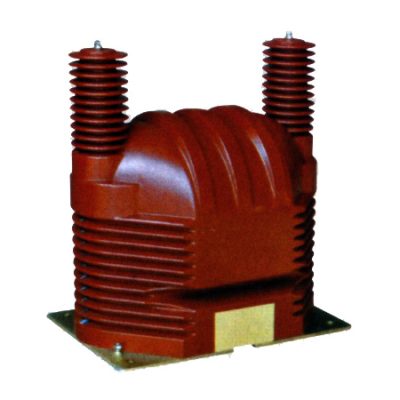
The UTF-8 is a high-reliability, dry-type current transformer (CT) designed for accurate current measurement and protective relaying in medium-voltage power systems operating at 11kV (IEC standard) or 10kV (domestic Chinese grid). Constructed using advanced vacuum pressure impregnation (VPI) cast-resin technology, the UTF-8 encapsulates its magnetic core and primary/secondary windings in a solid, non-flammable epoxy resin matrix. This design eliminates the fire hazards and maintenance burdens associated with traditional oil-immersed CTs while providing superior mechanical strength, moisture resistance, and long-term dielectric stability.
Operating Principle of Cast-Resin Insulation
Cast-resin insulation in the UTF-8 CT relies on a two-stage VPI process where the wound core assembly is first evacuated to remove air pockets, then impregnated under pressure with a cycloaliphatic epoxy resin system. The assembly is subsequently cured in an oven at controlled temperatures (typically 80–120°C), resulting in a monolithic, void-free structure. This process ensures uniform electric field distribution, minimizes partial discharge activity (<5 pC at 1.2 × Um/√3), and provides excellent tracking resistance (CTI > 600 V). The resin’s coefficient of thermal expansion closely matches that of copper and silicon steel, preventing microcracks during thermal cycling between –40°C and +40°C ambient conditions.
Advantages Over Oil-Immersed Designs
Compared to oil-filled CTs, the UTF-8 offers significant operational advantages. It requires no oil sampling, leak monitoring, or periodic topping-up, reducing lifecycle costs by up to 30%. Its self-extinguishing resin (UL 94 V-0 rated) eliminates fire propagation risks in confined indoor substations. Additionally, the absence of liquid insulation enables vertical or horizontal mounting without orientation constraints. The compact footprint—typically 180 mm height × 120 mm diameter for single-ratio models—facilitates retrofitting into legacy switchgear panels originally designed for oil units. Environmental compliance is enhanced as the unit contains no PCBs or hazardous liquids, simplifying end-of-life disposal per RoHS and WEEE directives.
Typical Applications Overview
The UTF-8 is engineered for critical roles in utility substations, industrial plants, and renewable energy interconnections. In 11kV ring main units (RMUs), it provides inputs to digital protective relays (e.g., overcurrent, earth-fault) with accuracy class 5P10 or 5P20. For revenue metering, variants with 0.2S or 0.5S accuracy support AMI deployments. Its robust design withstands frequent switching transients in arc furnace plants and variable load profiles in solar farms with inverters. The transformer’s short-time thermal current rating (Ith) of 20 kA/1s ensures survival during downstream faults without degradation.
Technical Specifications
The UTF-8 adheres to stringent electrical and environmental parameters defined by IEC 61869-2 and GB/T 20840.2. Key specifications are detailed below:
| Parameter | Value |
|---|---|
| Rated Voltage (Ur) | 11 kV (IEC) / 10 kV (GB) |
| System Highest Voltage (Um) | 12 kV |
| Primary Current (Ip) | 50–3000 A (standard); up to 6000 A (custom) |
| Secondary Current (Is) | 1 A or 5 A |
| Accuracy Classes | Metering: 0.2S, 0.5S; Protection: 5P10, 5P20, 10P10 |
| Rated Output (Sn) | 2.5–30 VA (per burden class) |
| Insulation Level | Power Frequency Withstand: 28 kV rms/1 min; Lightning Impulse: 75 kV peak |
| Short-Time Thermal Current (Ith) | 20 kA/1s (standard); 25 kA/1s (optional) |
| Dynamic Current (Idyn) | 50 kA peak |
| Ambient Temperature Range | –40°C to +40°C |
| Altitude Limit | ≤1000 m (derating required above 1000 m) |
| Relative Humidity | ≤95% (non-condensing) |
| Core Material | Grain-Oriented Electrical Steel (GOES), 0.3 mm thickness |
Standard Service Conditions
The UTF-8 is rated for continuous operation under IEC 60060-1 standard atmospheric conditions: temperature 20±15°C, pressure 101.3 kPa, and absolute humidity ≤11 g/m³. At altitudes exceeding 1000 m, the power frequency withstand voltage must be reduced by 1% per 100 m above sea level. For example, at 2000 m, the test voltage becomes 28 kV × (1 – 0.10) = 25.2 kV. Humidity tolerance extends to 95% RH provided condensation does not occur on terminals—a condition ensured by the hydrophobic nature of the cycloaliphatic resin surface.
Core and Winding Design
The magnetic circuit employs high-permeability GOES laminations (Bmax ≈ 1.7 T at 50 Hz) stacked in a toroidal configuration to minimize flux leakage. Secondary windings use enameled copper wire (Class F insulation, 155°C rating) with precise layer winding to control inter-turn capacitance. Primary conductors are either solid copper bars (for ≤600 A) or multi-stranded flexible cables (for >600 A) to mitigate skin effect losses. Burden compatibility is verified per IEC 61869-2 Annex B, ensuring phase error remains within ±10′ and ratio error within ±0.2% for 0.2S class at 20–120% of rated current.
Typical Applications
The UTF-8 serves diverse roles across power infrastructure, leveraging its dual compliance with international and domestic standards.
Substation Secondary Metering
In 11kV urban substations, UTF-8 units with 0.2S accuracy feed data to smart meters for time-of-use billing. Their low phase displacement (<5' at 100% In) ensures minimal reactive energy measurement error. For instance, a 400/5 A, 0.2S CT supplies a Class 0.5S meter in a commercial building’s main incomer, enabling demand-side management with ±0.3% total system accuracy. The cast-resin housing resists ozone degradation from nearby switchgear operations, maintaining calibration stability over 10-year intervals.
Industrial Power Distribution
Heavy industries like steel mills deploy UTF-8 CTs (5P20 class) on motor feeder circuits rated 11kV/1250 A. These units endure frequent inrush currents (up to 8× In) during motor starts without saturation, thanks to a knee-point voltage (Vk) ≥ 150 V. The 30 VA output drives both overcurrent relays and power quality analyzers simultaneously. In chemical plants, the resin’s resistance to corrosive atmospheres (tested per IEC 60068-2-43) prevents terminal oxidation that could compromise secondary signals.
Renewable Energy Integration
Solar photovoltaic (PV) farms use UTF-8 CTs on 11kV collector feeders to monitor string inverter output. The transformer’s wide linear range (5–120% In) captures low-irradiance generation accurately, while its high saturation margin handles transient overcurrents during grid reconnection. A typical 10 MW plant employs 630/1 A, 0.5S units feeding SCADA systems for performance ratio calculations. The absence of oil eliminates contamination risks in environmentally sensitive sites.
Rural and Suburban Distribution Networks
In rural 10kV networks (equivalent to 11kV IEC), pole-mounted UTF-8 CTs enable automated fault location. Paired with reclosers, 5P10-class units detect high-impedance earth faults (as low as 30 A) through residual current summation. Their –40°C cold-start capability ensures reliability in northern climates, while UV-stabilized resin prevents surface chalking after 15 years of outdoor exposure. Utilities report 40% fewer false trips compared to older oil-filled models due to improved transient response.
Compliance with International Standards
The UTF-8 is certified to IEC 61869-2:2012 (“Instrument transformers – Part 2: Additional requirements for current transformers”) and fully aligns with China’s GB/T 20840.2-2014, which adopts IEC 61869-2 with minor national deviations.
IEC 61869-2 Compliance Details
Key IEC 61869-2 requirements met include: temperature rise limits (≤60 K for windings at 1.2× In), short-circuit withstand (Ith and Idyn per Table 102), and accuracy verification under specified burdens. The standard mandates ratio and phase error testing at 5%, 20%, 100%, and 120% of rated current for metering classes, and at rated accuracy limit factor (ALF) for protection classes. Partial discharge measurements are performed at 1.2 × Um/√3 with acceptance criteria ≤10 pC for resin-insulated CTs.
GB/T 20840.2 Alignment and Differences
GB/T 20840.2 mirrors IEC 61869-2 but specifies 10kV as the nominal system voltage (vs. 11kV in IEC). Consequently, the lightning impulse level is 75 kV in both standards, but the power frequency test voltage is 30 kV rms/1 min for GB (vs. 28 kV for IEC 11kV). Domestic certification also requires type tests per DL/T 725, including seismic withstand (0.3g horizontal acceleration). Notably, GB permits 0.2 accuracy class (non-S) for metering, whereas IEC mandates 0.2S for revenue applications below 5% In.
Testing and Certification Requirements
Type testing per IEC 61869-2 includes: temperature rise (Clause 7.3), short-circuit (Clause 7.4), accuracy (Clause 7.5), and insulation (Clause 7.6). Routine tests for every UTF-8 unit comprise: visual inspection, power frequency withstand (28 kV/1 min), turns ratio verification (±0.25% tolerance), and polarity check. Certification is issued by accredited bodies (e.g., KEMA, CESI, or CEPREI) with test reports traceable to SI units.
On-Site Testing Procedures
Field commissioning of the UTF-8 requires standardized tests to verify integrity after transport and installation.
Insulation Resistance Test
Using a 2500 V DC megohmmeter, measure insulation resistance between primary-to-secondary, primary-to-ground, and secondary-to-ground. Acceptance criteria: ≥1000 MΩ at 20°C. Correct for temperature using RT2 = RT1 × 2(T1–T2)/10. Values below 500 MΩ indicate moisture ingress or resin cracking, requiring drying or replacement. Perform before any high-voltage tests to avoid damaging compromised insulation.
Turns Ratio Test
Apply a low-voltage AC source (5–50 V) to the primary and measure secondary voltage. Calculate ratio as Vp/Vs and compare to nameplate. Tolerance: ±0.25% for metering classes, ±0.5% for protection. For multi-ratio CTs, test all tap combinations. Use a dedicated ratio tester (e.g., Omicron CT Analyzer) to eliminate lead resistance errors. Discrepancies >1% suggest inter-turn shorts or incorrect tapping.
Polarity Test
Verify reducing polarity per IEC 61869-2 Figure 101. Connect a 1.5–6 V DC battery across P1–P2 and observe secondary voltage direction with a center-zero galvanometer. Momentary closure should show positive deflection at S1 relative to S2. Incorrect polarity causes relay misoperation—e.g., differential protection tripping during external faults. Re-test if secondary wiring was disturbed during panel modifications.
Power Frequency Withstand Voltage Test
Apply 28 kV rms (50 Hz) for 1 minute between primary and grounded secondary/core. Ramp up at ≤1 kV/s. Monitor for flashover, excessive leakage current (>1 mA), or audible discharge. Reduce voltage gradually post-test. This validates resin integrity after mechanical stress during shipping. Never perform if insulation resistance is <500 MΩ. For refurbished units, use 80% of factory test voltage (22.4 kV).
Short-Circuit Test (for CTs)
Unlike VTs, CTs require a short-circuit test to confirm thermal withstand. Inject rated primary current (Ip) for 1 second while monitoring secondary voltage. Ensure it remains below the knee-point voltage (Vk). Post-test, recheck ratio and insulation resistance. Significant deviation indicates core damage. This test is typically omitted during routine maintenance but mandatory after fault events exceeding 50% of Ith.
Preventive Maintenance Guide
Proactive maintenance extends UTF-8 service life to 25–30 years while ensuring measurement fidelity.
Periodic Inspection Schedule
Conduct annual visual inspections: check for resin cracks, terminal corrosion, or tracking marks. Clean surfaces with isopropyl alcohol if contaminated by dust or salt. Every 5 years, perform full electrical tests (insulation resistance, ratio, polarity). After any system fault >10 kA, execute immediate post-fault diagnostics. Log all results in asset management systems to trend degradation—e.g., insulation resistance decline >20%/year warrants investigation.
Maintenance Intervals and Fault Diagnosis
| Interval | Activities | Fault Indicators |
|---|---|---|
| Annual | Visual check, terminal torque verification (2.5 N·m for M6 screws), cleaning | Discoloration, arcing sounds, overheating smell |
| 5-Year | Full electrical tests, burden verification, secondary loop continuity | Ratio error >0.5%, insulation <1000 MΩ |
| Post-Fault | Short-circuit test, core remanence check (demagnetize if needed) | Relay misoperation, abnormal noise |
Common faults include open secondary circuits (causing dangerous overvoltages) and core saturation from excessive burden. Always short-circuit secondary terminals before disconnecting meters. Demagnetization is required if hysteresis loops show remanence >10% of Bmax, using a variable AC source ramped down from 1.5× In.
Conclusion
The UTF-8 11kV cast-resin current transformer represents a benchmark in medium-voltage instrumentation, combining IEC 61869-2 and GB/T 20840.2 compliance with robust engineering for demanding substation environments. Its VPI epoxy resin construction eliminates fire risks and maintenance overhead inherent in oil-immersed alternatives, while GOES core technology ensures metrological precision across metering (0.2S) and protection (5P20) applications. Field-proven reliability stems from rigorous type testing—including 28 kV power frequency withstand and 20 kA thermal current ratings—and adherence to exacting manufacturing tolerances (±0.25% ratio error). Designed for 25–30 years of service under –40°C to +40°C conditions, the UTF-8 supports modern grid needs from urban smart metering to renewable integration. Its compact form factor facilitates seamless upgrades in existing 10kV/11kV infrastructure, and standardized testing protocols ensure consistent performance validation throughout its lifecycle. For utilities and industrial operators prioritizing safety, accuracy, and total cost of ownership, the UTF-8 delivers uncompromised technical excellence aligned with global best practices.
Frequently Asked Questions (FAQ)
Q1: Can the UTF-8 be used on a 10kV domestic system?
Yes. While rated for 11kV per IEC standards, the UTF-8 is fully compatible with 10kV Chinese distribution networks (GB system). Its insulation levels (28 kV power frequency, 75 kV lightning impulse) exceed GB/T 20840.2 requirements for 10kV equipment.
Q2: What is the maximum allowable secondary burden for a 0.2S class UTF-8?
Burden depends on the specific model’s rated output (e.g., 10 VA). For a 400/5 A, 0.2S, 10 VA CT, the maximum impedance is Zb = Sn/Is² = 10/25 = 0.4 Ω. Exceeding this increases ratio error beyond ±0.2% at 100% In.
Q3: How often should insulation resistance be tested?
Annually during routine substation maintenance. After any fault event or if visual inspection reveals contamination, test immediately. Record values corrected to 20°C to establish degradation trends.
Q4: Is demagnetization required after every short-circuit test?
Only if core remanence is suspected—indicated by elevated ratio error or relay malfunctions. Verify by measuring excitation current; if it exceeds 10% of nominal at 100% Vk, demagnetize using a decaying AC waveform.
Q5: Can multiple UTF-8 CTs share a common ground point?
No. Each CT secondary circuit must have a single, dedicated ground at the relay panel per IEC 61869-2 Clause 8.3.3 to prevent circulating currents and ensure ground-fault sensitivity.
Q6: What torque should be applied to secondary terminals?
Use 2.5 N·m for M6 brass terminals. Over-torquing (>3 N·m) can crack the resin housing; under-torquing (<2 N·m) increases contact resistance, causing heating and measurement errors.