Article Content
For Substation Metering & Protection: JDZW-35 11kV Cast-Resin Current Transformer per IEC 61869-2
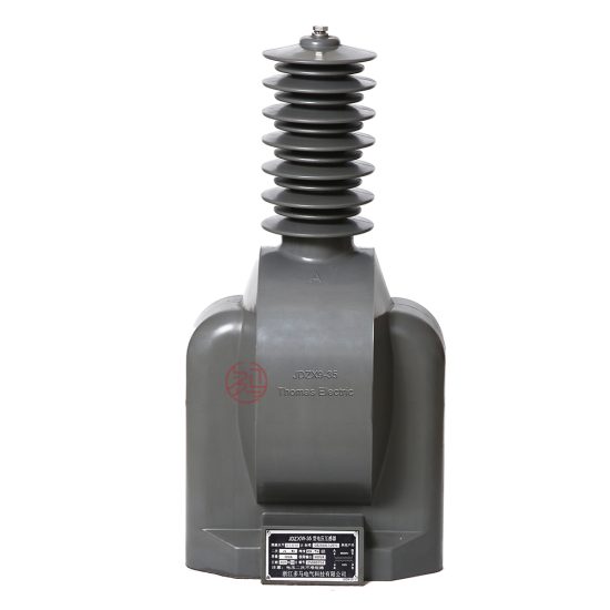
Introduction to the JDZW-35 Current Transformer
The JDZW-35 is a high-reliability, indoor-type cast-resin current transformer (CT) engineered for accurate current measurement and protective relay coordination in 11kV (IEC-rated) or 10kV (domestic Chinese system) medium-voltage networks. Designed in strict compliance with IEC 61869-2 and GB/T 20840.2, this instrument transformer leverages vacuum pressure impregnation (VPI) epoxy resin technology to encapsulate its magnetic core and windings, ensuring long-term dielectric integrity and mechanical robustness.
Operating Principle of Cast-Resin Insulation
Cast-resin insulation in the JDZW-35 employs a two-component cycloaliphatic epoxy resin system cured under vacuum and pressure. This process eliminates air voids and moisture ingress pathways, critical for maintaining consistent dielectric strength over decades of service. The resin matrix fully embeds the primary conductor, secondary windings, and the grain-oriented electrical steel (GOES) core, creating a monolithic structure resistant to partial discharge (PD) activity below 10 pC at rated voltage—well within IEC 61869-2 limits. Unlike oil-filled alternatives, the solid insulation eliminates fire hazards, environmental contamination risks, and maintenance-intensive oil sampling. The thermal class of the resin system is typically F (155°C), enabling stable operation under continuous load and short-circuit conditions without degradation.
Advantages Over Oil-Immersed Designs
Compared to traditional oil-immersed CTs, the JDZW-35 offers significant operational and safety benefits. Its dry-type construction eliminates the need for oil containment systems, reducing footprint and simplifying installation in confined indoor switchgear bays. The absence of flammable oil enhances fire safety in urban substations and industrial facilities where regulatory codes restrict combustible materials. Additionally, cast-resin CTs exhibit superior resistance to humidity and pollution, making them ideal for coastal or high-humidity environments. Mechanical stability is enhanced through the rigid epoxy housing, which dampens vibration-induced winding displacement—a common failure mode in oil units during fault currents. Lifecycle cost analysis consistently shows lower total ownership costs due to zero fluid maintenance, extended inspection intervals, and higher reliability.
Typical Applications Overview
The JDZW-35 is predominantly deployed in indoor 35kV-class switchgear (rated for 11kV/10kV system voltage) across utility distribution substations, industrial power centers, and renewable energy interconnection points. Its dual-winding configuration supports simultaneous metering (e.g., 0.5 class) and protection (e.g., 5P10 or 10P15) functions, eliminating the need for multiple transformers. Common installations include ring main units (RMUs), metal-clad switchboards, and generator step-up (GSU) transformer secondary circuits. The unit’s compact dimensions (typically ≤300 mm height) facilitate retrofitting into legacy panels originally designed for oil-filled CTs, providing a modernization path without major civil works.
Technical Specifications
The JDZW-35 delivers precision performance under defined electrical and environmental parameters. All specifications align with IEC 61869-2 (2012) and GB/T 20840.2 (2014), ensuring global interoperability and local regulatory acceptance.
Rated Electrical Parameters
Key electrical ratings include: System voltage (Um) = 12 kV (corresponding to 11kV nominal IEC system); Domestic system voltage = 10kV; Primary current (Ip) = 50–2000 A (standard ratios: 100/5, 200/5, 400/5, 600/5, etc.); Secondary current = 1 A or 5 A; Accuracy classes: 0.2S/0.5 for metering, 5P10/10P15 for protection; Rated burden = 10–30 VA per winding; Short-time thermal current = 20–40 kA for 1 s; Dynamic withstand current = 50–100 kA peak. Insulation level per IEC 60071-1: Power frequency withstand = 28 kV rms (1 min); Lightning impulse withstand = 75 kV peak (1.2/50 μs). These values ensure compatibility with standard 35kV-class switchgear test protocols.
Core and Winding Construction
The magnetic circuit utilizes high-permeability GOES (M6 or equivalent) laminations, annealed to minimize hysteresis loss and core remanence. Core cross-section is optimized to avoid saturation at 20× rated current for protection windings. Secondary windings are wound with oxygen-free copper (OFC) wire, insulated with Class F (155°C) enamel, and embedded in the resin matrix to prevent movement under electromagnetic forces. Primary conductors are either solid copper bars (for lower ratios) or multi-turn coils (for high-ratio units), all fully encapsulated. Partial discharge inception voltage exceeds 1.2× Um/√3, with extinction below 1.1× Um/√3, per IEC 61869-2 clause 8.5.
Standard Service Conditions
The JDZW-35 is rated for indoor use under the following ambient conditions: Temperature range = –25°C to +40°C (daily average ≤35°C); Relative humidity = up to 95% non-condensing; Altitude = ≤1000 m above sea level (derating required above 1000 m per IEC 60071-2); Pollution degree = III (moderate); Seismic zone = up to 0.3g horizontal acceleration. Installation must ensure adequate clearance from grounded parts (≥125 mm for 11kV phase-to-ground) and avoidance of mechanical stress on terminals. The transformer is not suitable for outdoor exposure without additional IP-rated enclosures.
Typical Applications
The JDZW-35 serves critical roles across diverse power infrastructure segments, leveraging its dual-function capability and robust construction.
Substation Secondary Metering
In utility-owned 11kV/10kV distribution substations, the JDZW-35 provides revenue-grade metering via its 0.2S or 0.5 accuracy class winding. Connected to digital energy meters or SCADA RTUs, it enables precise billing and load profiling. For example, a 400/5 ratio unit with 15 VA burden at 0.2S class ensures measurement error remains within ±0.2% at 100% load and ±0.35% at 20% load—critical for detecting energy theft or unbalanced loading. The cast-resin design prevents drift caused by oil aging, ensuring calibration stability over 10-year intervals mandated by regulatory authorities.
Industrial Power Distribution
Within manufacturing plants and data centers, the JDZW-35 interfaces with protective relays (e.g., overcurrent, earth-fault) using its 5P10 winding. During a downstream fault, the CT must maintain linear output up to 10× rated current (e.g., 4000 A for a 400/5 unit) with composite error ≤5%. This enables selective tripping without nuisance operations. In arc-flash mitigation schemes, fast-acting relays rely on the CT’s low leakage inductance and minimal phase shift (<±10 minutes at rated current) to achieve clearing times under 100 ms.
Renewable Energy Integration
Solar PV and wind farms frequently use JDZW-35 units at the point of interconnection (POI) to grid-tied inverters or step-up transformers. Here, the CT supports both anti-islanding protection (via vector shift detection) and export/import metering. The low remanence of the GOES core is essential for accurate measurement during rapid load fluctuations inherent in renewable generation. Units are often specified with 1 A secondary current to reduce copper losses over long cable runs to control rooms.
Rural and Suburban Distribution Networks
In remote or space-constrained rural substations, the JDZW-35’s compact size and maintenance-free operation reduce OPEX. Its immunity to oil leaks makes it ideal for pole-mounted or pad-mounted switchgear where environmental regulations prohibit hydrocarbon fluids. Dual-ratio windings (e.g., 200–400/5) allow future load growth without hardware replacement—simply by reconfiguring secondary taps during routine outages.
Generator and Motor Protection Circuits
For on-site generation (e.g., diesel gensets) or large induction motors (>1 MW), the JDZW-35 provides differential or overload protection. High knee-point voltage (typically >150 V for 5P10 class) ensures sufficient excitation margin during internal faults. The solid insulation withstands repeated motor starting inrush currents (6–8× rated) without cumulative damage, unlike oil units prone to gassing under thermal cycling.
Compliance with International Standards
Conformance to IEC 61869-2 and GB/T 20840.2 validates the JDZW-35’s performance, safety, and interoperability across global markets.
IEC 61869-2 Certification Requirements
IEC 61869-2 specifies type, routine, and special tests for instrument transformers. The JDZW-35 undergoes mandatory type tests including temperature rise (≤60 K for windings), short-circuit withstand (thermal and dynamic), and partial discharge (≤10 pC at 1.2 Um/√3). Routine tests per clause 10 include: power frequency withstand (28 kV/1 min), turns ratio verification (±0.25% tolerance), polarity check (reducing polarity confirmed), and insulation resistance (>1000 MΩ at 2500 V DC). Certification requires third-party witness testing by accredited labs (e.g., KEMA, CESI) with documentation traceable to SI units.
Alignment with GB/T 20840.2
China’s GB/T 20840.2 mirrors IEC 61869-2 but includes localized requirements: altitude derating factors for installations >1000 m, stricter seismic testing (0.4g for Zone 8), and mandatory domestic type approval from CEPREI or SGCC. Notably, GB/T permits 10kV system voltage labeling while IEC mandates 11kV—both refer to the same physical unit rated for Um=12 kV. Burden definitions also differ slightly: GB uses “VA” while IEC specifies “Zb” in ohms, though conversion is straightforward (Zb = VA / Is²).
Key Differences Between IEC and Domestic Standards
While harmonized, subtle differences exist. GB/T 20840.2 requires additional salt fog testing for coastal applications (96-hour exposure per IEC 60068-2-11), whereas IEC 61869-2 references general environmental standards. Accuracy class notation is identical (e.g., 0.5, 5P10), but GB mandates factory calibration certificates stamped by provincial metrology bureaus. For export units, dual labeling (“11kV/10kV”) is common. Crucially, both standards prohibit open-circuit operation of CT secondaries—a safety feature enforced via terminal shorting links during maintenance.
On-Site Testing Procedures
Post-installation and periodic field tests verify integrity and performance per IEC 60270 and IEEE C57.13.6 guidelines.
Insulation Resistance Test
Using a 2500 V DC megohmmeter, measure insulation resistance between primary-to-secondary, primary-to-ground, and secondary-to-ground. Acceptance criterion: ≥1000 MΩ at 20°C. Correct for temperature using RT2 = RT1 × 2(T1–T2)/10. Low readings (<100 MΩ) indicate moisture ingress or resin cracking—requiring drying or replacement. Always discharge windings after testing to prevent residual charge hazards.
Turns Ratio Test
Apply low-voltage AC (5–10 V) to the secondary winding and measure induced primary voltage. Calculate ratio as Vp/Vs; compare to nameplate. Tolerance: ±0.25% for metering classes, ±0.5% for protection. Alternatively, use a dedicated ratio tester injecting 1–5 A into the primary. Deviations >1% suggest turn-to-turn shorts or incorrect tap selection—common after improper handling during shipping.
Polarity Verification
Confirm reducing polarity (IEC standard) using a 1.5 V DC battery and analog ammeter. Connect (+) to P1 and (–) to P2; momentarily close the circuit. A positive kick on the ammeter connected to S1–S2 confirms correct polarity. Reversed polarity causes 180° phase error, leading to false tripping in differential schemes. Document results with timestamped photos for audit trails.
Power Frequency Withstand Voltage Test
Apply 28 kV rms (50 Hz) between primary and grounded secondary/enclosure for 1 minute. Use a calibrated HV test set with overcurrent trip (≤100 mA). Failure (flashover or excessive leakage current >10 mA) indicates insulation degradation. Perform only after insulation resistance passes. Reduce voltage gradually post-test to avoid transient overvoltages.
Short-Circuit Test for CT Performance
Inject 10–20× rated current (e.g., 4000 A for 400/5) into the primary using a portable test set. Monitor secondary voltage across a burden resistor matching nameplate VA. For a 5P10 class, Vs must remain linear (error ≤5%) up to 10× In. Saturation manifests as voltage flattening—indicating inadequate knee-point voltage. This test validates protection coordination settings without requiring full fault simulation.
Preventive Maintenance Guide
A structured maintenance program extends service life beyond 25 years while ensuring safety and accuracy.
Annual Visual and Functional Inspection
Inspect for surface cracks, tracking marks, or discoloration on the resin housing. Check terminal tightness (torque: 15–20 N·m for M8 bolts) and corrosion on copper pads. Verify secondary shorting links are secure when disconnected. Clean dust with dry, lint-free cloth—never solvents. Record ambient temperature and load current trends; sustained operation >80% rated may warrant thermal imaging to detect hot spots.
Five-Year Comprehensive Maintenance Schedule
Every 60 months, perform: insulation resistance retest, ratio/polarity verification, and burden measurement. Use a micro-ohmmeter to check secondary winding resistance (compare to baseline ±2%). If installed in high-pollution areas, conduct hydrophobicity testing of the resin surface (contact angle >90° indicates good condition). Replace silica gel breathers if present (though rare in cast-resin units). Update maintenance logs with test certificates traceable to national standards.
Fault Diagnosis and Troubleshooting
Common issues include: (1) Ratio drift—caused by core demagnetization after fault; remedy with degaussing cycle. (2) High PD levels—indicate internal voids; requires factory refurbishment. (3) Terminal overheating—due to loose connections; retorque and apply antioxidant paste. Never operate with open secondary—this induces dangerous overvoltages (>10 kV) risking insulation failure. Maintain spare shorting links onsite for emergency isolation.
| Maintenance Interval | Tasks | Acceptance Criteria |
|---|---|---|
| Annual | Visual inspection, terminal check, IR scan | No cracks, temp rise ≤15 K above ambient |
| 5 Years | Insulation resistance, ratio test, burden check | IR ≥1000 MΩ, ratio error ≤0.5% |
| 10 Years | Partial discharge measurement (if available) | PD ≤15 pC at 1.1 Um/√3 |
Conclusion
The JDZW-35 11kV cast-resin current transformer represents a benchmark in medium-voltage instrumentation, combining IEC 61869-2 compliance with practical engineering excellence. Its VPI epoxy resin encapsulation eliminates the fire, environmental, and maintenance liabilities of oil-filled alternatives while delivering exceptional accuracy for both metering (0.2S/0.5 class) and protection (5P10/10P15) applications. Constructed with GOES silicon steel cores and oxygen-free copper windings, the unit maintains performance stability across 25–30 years of service under standard indoor conditions. Rigorous adherence to international (IEC) and domestic (GB) standards ensures seamless integration into global power systems—from urban substations to remote renewable sites. Field-proven testing and maintenance protocols further guarantee operational reliability, minimizing unplanned outages and lifecycle costs. For engineers specifying or maintaining 11kV/10kV networks, the JDZW-35 offers a technically sound, code-compliant solution that balances precision, safety, and longevity without compromise.
Frequently Asked Questions (FAQ)
Q1: Can the JDZW-35 be used in 10kV systems labeled as 11kV?
A: Yes. The JDZW-35 is rated for Um = 12 kV, making it suitable for both 11kV (IEC) and 10kV (Chinese domestic) systems. The physical unit is identical; only labeling differs per market.
Q2: What is the maximum allowable secondary burden for a 5P10 class winding?
A: The burden must not exceed the nameplate value (e.g., 15 VA). Exceeding this reduces the knee-point voltage, potentially causing saturation during faults. Calculate total burden as Ztotal = Zwire + Zrelay + Zcontact.
Q3: How often should insulation resistance be tested?
A: Annually during routine inspections, and after any abnormal event (e.g., nearby fault, flooding). Acceptance threshold is ≥1000 MΩ at 2500 V DC.
Q4: Is the JDZW-35 suitable for outdoor installation?
A: No—it is rated for indoor use only. Outdoor applications require an IP54-rated enclosure or a dedicated outdoor CT model.
Q5: What causes ratio errors exceeding 0.5%?
A: Common causes include turn-to-turn shorts, core remanence after fault currents, or incorrect tap selection. Perform degaussing and retest; if unresolved, replace the unit.
Q6: Can I leave the secondary open during maintenance?
A: Absolutely not. Always install shorting links across S1–S2 before disconnecting loads. Open-circuit operation generates hazardous overvoltages that can destroy insulation.