Article Content
Introduction to the UTF-8 Voltage Transformer
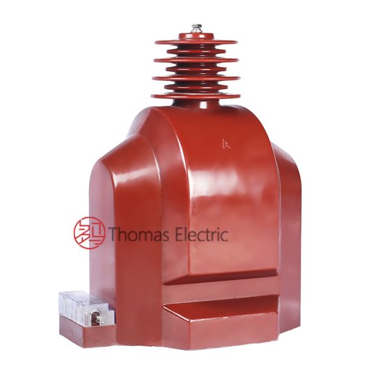
The UTF-8 is a single-phase, indoor/outdoor-rated cast-resin voltage transformer (VT) engineered for high-reliability operation in 33kV transmission and distribution networks. Designed in strict accordance with IEC 61869-3 and GB/T 20840.3, it serves critical roles in metering, protection, and monitoring systems within modern substations. Unlike legacy oil-immersed designs, the UTF-8 employs vacuum pressure impregnation (VPI) epoxy resin technology to fully encapsulate its magnetic core and windings, eliminating fire hazards, oil leakage risks, and environmental contamination concerns.
Operating Principle of Cast-Resin Insulation
Cast-resin insulation in the UTF-8 VT utilizes a cycloaliphatic epoxy resin system cured under controlled temperature and vacuum conditions. This process ensures complete void-free encapsulation of the primary and secondary windings wound around a grain-oriented electrical steel (GOES) core. The absence of air pockets prevents partial discharge inception below 10 pC at rated voltage—well within IEC 61869-3 limits. The resin’s high dielectric strength (≥20 kV/mm) and thermal conductivity (0.8–1.2 W/m·K) enable stable performance under continuous load and transient overvoltages. Additionally, the coefficient of thermal expansion closely matches that of copper and steel, minimizing mechanical stress during thermal cycling between –40°C and +40°C ambient conditions.
Advantages Over Oil-Immersed Designs
Compared to traditional oil-filled VTs, the UTF-8 offers significant operational and safety benefits. It requires no oil containment systems, reducing civil works costs and eliminating fire risk—critical for urban or indoor substations. Maintenance intervals are extended due to the hermetic seal provided by the resin, which prevents moisture ingress and winding oxidation. The unit’s compact footprint (typically 30% smaller than equivalent oil units) simplifies integration into space-constrained switchgear bays. Furthermore, the absence of flammable materials allows installation in confined spaces without ventilation requirements, aligning with IEC 61869-3’s emphasis on environmental and personnel safety.
Typical Applications Overview
The UTF-8 is deployed across utility and industrial power systems where precision voltage transformation is essential. Primary applications include revenue metering at 33kV/√3 : 100/√3 V or 110/√3 V ratios, feeder protection relaying (e.g., overvoltage, undervoltage, and directional earth fault schemes), and synchro-check circuits in grid interconnection points. Its robust design supports operation in harsh environments—including coastal areas with salt fog (IEC 60068-2-52 severity level 6) and high-altitude sites up to 2000 m above sea level—without derating. The transformer’s low phase error (< ±10 arcmin) and ratio error (< ±0.2% at 0.2 accuracy class) ensure compliance with Class 0.2/3P specifications for combined metering and protection duties.
Technical Specifications
The UTF-8 voltage transformer is engineered to deliver precise, stable performance under defined service conditions. All parameters adhere to IEC 61869-3:2011 and GB/T 20840.3-2013, ensuring global interoperability.
| Parameter | Value |
|---|---|
| System Voltage (IEC) | 33 kV |
| System Voltage (Domestic) | 35 kV |
| Rated Primary Voltage | 33/√3 kV (phase-to-earth) |
| Rated Secondary Voltages | 100/√3 V, 110/√3 V (standard); 100 V, 110 V (optional) |
| Voltage Ratio | 33,000/√3 : 100/√3 V (e.g., 19052 V : 57.7 V) |
| Accuracy Classes | Metering: 0.2, 0.5; Protection: 3P, 6P |
| Rated Output (per burden) | 30 VA (0.2 class), 50 VA (3P class) |
| Insulation Level (LI/AC) | 170 kV / 70 kV (per IEC 60071-1) |
| Partial Discharge | < 10 pC at 1.2 × Ur/√3 |
| Core Material | GOES (Grain-Oriented Electrical Steel), M4 grade |
| Insulation System | VPI Epoxy Resin, UL 94 V-0 flame rating |
| Ambient Temperature Range | –40°C to +40°C |
| Altitude Limit | ≤ 2000 m (no derating) |
| Relative Humidity | Up to 95% non-condensing |
Standard Service Conditions
The UTF-8 is rated for continuous operation under standard service conditions as defined in Clause 5 of IEC 61869-3. Ambient temperature must not exceed +40°C (24-hour average ≤ +35°C), with a minimum of –40°C for cold-climate variants. Relative humidity may reach 95% provided condensation does not occur on the housing surface. Installation altitude is limited to 2000 meters; beyond this, external insulation must be adjusted per IEC 60071-2. The transformer assumes a symmetrical three-phase system with maximum sustained overvoltage of 1.2 × Ur/√3 for metering windings and 1.9 × Ur/√3 for 30 seconds on protection windings—critical for ferroresonance mitigation in isolated neutral systems.
Accuracy and Burden Characteristics
Accuracy performance is validated at rated frequency (50 Hz or 60 Hz) and specified burdens. For a 0.2 accuracy class winding, ratio error must not exceed ±0.2% and phase displacement ≤ ±10 arcmin at 25–100% of rated burden. Protection windings (3P class) tolerate ±3% ratio error and ±120 arcmin phase error at 100% burden under 1.2 × Ur/√3. Burden is expressed in volt-amperes (VA) at cos φ = 0.8 lagging. Exceeding rated burden degrades accuracy nonlinearly; for example, operating a 30 VA winding at 40 VA may increase ratio error to ±0.35%. Terminal markings follow IEC 61869-3: A, N (primary); a, n (secondary).
Typical Applications
The UTF-8 voltage transformer’s versatility stems from its dual-certification (IEC and GB) and robust construction, enabling deployment across diverse power infrastructure segments.
Substation Secondary Metering
In 33kV primary substations, the UTF-8 provides scaled-down voltage signals to revenue-class energy meters (e.g., IEC 62053-22 Class 0.2S). Its low thermal drift ensures billing accuracy over seasonal temperature swings. For instance, in a 100 MW industrial feeder, a ±0.2% ratio error translates to less than 0.2 kWh deviation per MWh—critical for regulatory compliance. The transformer’s secondary terminals connect directly to meter test blocks, facilitating calibration without service interruption. Redundant windings (e.g., one 0.2 class + one 3P class) allow simultaneous metering and protection functions, optimizing panel space.
Industrial Power Distribution
Large manufacturing plants with 33kV internal distribution use the UTF-8 for motor protection relays (e.g., 27/59 functions) and power quality monitoring. In steel mills or data centers, where voltage sags can trigger costly shutdowns, the VT’s fast response (< 1 ms rise time) enables precise event capture. The cast-resin housing resists chemical vapors and dust (IP54 rating with optional gasketing), outperforming oil units in corrosive environments. A typical installation includes three single-phase UTF-8 units connected in wye configuration to feed a multifunction relay like SEL-351S.
Renewable Energy Integration
Solar farms and wind parks connecting to 33kV grids rely on the UTF-8 for grid-code compliance testing. During low-voltage ride-through (LVRT) events, the VT accurately reproduces grid voltage dips down to 15% of nominal for 150 ms, enabling correct inverter response validation. Its linear B-H curve (saturation flux density > 1.8 T) prevents harmonic distortion during transient recovery. In China, UTF-8 units certified to GB/T 20840.3 are mandated for all new renewable interconnections per NDRC Order No. 14.
Rural and Suburban Distribution Networks
For utilities upgrading aging 35kV rural networks (domestic equivalent of 33kV IEC systems), the UTF-8 offers plug-and-play replacement of oil-filled VTs. Its lightweight design (≈85 kg) simplifies pole-top or pad-mounted installation using standard brackets. In regions with frequent lightning (e.g., Southeast Asia), the 170 kV lightning impulse withstand level protects downstream equipment. Remote monitoring via SCADA is enabled by clean secondary waveforms free from oil degradation artifacts.
Compliance with International Standards
The UTF-8 voltage transformer meets stringent requirements of both international and Chinese national standards, ensuring global acceptance and interoperability.
IEC 61869-3 Compliance Details
IEC 61869-3:2011 (“Instrument transformers – Part 3: Additional requirements for inductive voltage transformers”) governs the UTF-8’s design, testing, and marking. Key compliance aspects include: thermal stability verified by temperature-rise tests (winding rise ≤ 60 K above ambient at 1.2 × rated output); short-circuit withstand capability (withstanding 25 × rated current for 1 s without damage); and electromagnetic compatibility (EMC) immunity per IEC 61000-4 series. The standard mandates type tests (e.g., temperature rise, short-circuit), routine tests (ratio, polarity, insulation), and special tests (partial discharge, capacitance/tan δ). All UTF-8 units undergo 100% routine testing before shipment.
GB/T 20840.3 Alignment
GB/T 20840.3-2013 (“Instrument transformers – Part 3: Additional requirements for inductive voltage transformers”) mirrors IEC 61869-3 but includes China-specific provisions. Notably, GB requires enhanced seismic withstand (horizontal acceleration 0.3g per GB/T 13540), stricter partial discharge limits (< 5 pC for 0.2 class), and mandatory third-party certification by CEPREI or CESI China. The UTF-8’s core lamination uses domestic M4-grade GOES steel meeting YB/T 127-1997, ensuring local supply chain compliance. Domestic 35kV system voltage is accommodated via identical insulation coordination—Ur = 35/√3 kV primary with LI/AC = 185/85 kV for GB-marked units.
Key Differences Between IEC and Domestic Standards
While harmonized, IEC 61869-3 and GB/T 20840.3 diverge in three areas: (1) Altitude correction—GB applies derating above 1000 m vs. IEC’s 2000 m threshold; (2) Pollution severity—GB mandates creepage distance ≥ 25 mm/kV for heavy industrial zones (vs. IEC’s 20 mm/kV); (3) Marking requirements—GB units must display CCC certification mark and domestic model number (JDZX9-35) alongside UTF-8. Despite these, the UTF-8’s modular design allows single-platform production for both markets by adjusting resin formulation and terminal labeling.
On-Site Testing Procedures
Post-installation and periodic field testing ensures the UTF-8 operates within specified tolerances. All procedures follow IEC 61869-3 Annex D and IEEE C57.13.2 guidelines.
Insulation Resistance Test
Measure insulation resistance between primary winding and ground, and between primary and secondary windings, using a 2500 V DC megohmmeter. Acceptance criteria: ≥10,000 MΩ at 20°C. Correct for temperature using RT2 = RT1 × 2(T1–T2)/10. Values below 5000 MΩ indicate moisture ingress or resin cracking. Perform before and after power frequency withstand tests to detect insulation degradation. Ensure secondary terminals are shorted and grounded during measurement to avoid false readings from capacitive coupling.
Turns Ratio Test
Apply 100–500 V AC (50/60 Hz) to the primary winding and measure secondary voltage with a calibrated voltmeter (±0.1% accuracy). Calculate actual ratio: Vp/Vs. Compare to nameplate ratio; tolerance is ±0.2% for 0.2 class windings and ±3% for 3P class. Use a dedicated turns ratio tester (e.g., Omicron CT Analyzer) for automated comparison. Deviations > tolerance suggest inter-turn shorts or incorrect tap selection. Always verify at multiple voltage levels (25%, 50%, 100% of test voltage) to detect nonlinear core behavior.
Polarity Test
Confirm reducing polarity per IEC 61869-3 Figure 102. Connect a 6–12 V battery between primary terminals A (+) and N (–). Momentarily close the circuit while monitoring secondary terminals a and n with an analog DC voltmeter. A momentary positive deflection indicates correct polarity (a corresponds to A). Digital multimeters may not capture transient response; use analog or oscilloscope. Incorrect polarity causes 180° phase reversal, leading to relay misoperation or metering errors. Document results with timestamped oscillograms for audit trails.
Power Frequency Withstand Voltage Test
Apply 70 kV RMS (for 33kV system) at 50 Hz between primary and grounded tank/secondary for 1 minute. Ramp voltage at ≤1 kV/s to avoid transient overvoltages. Leakage current must remain < 10 mA. Failure (flashover or breakdown) indicates insulation defects. For maintenance testing, use 80% of factory test voltage (56 kV) per IEC 60270. Always isolate VT from connected equipment; disconnect secondary leads and ground unused terminals. Perform only in dry conditions (RH < 80%) to prevent surface tracking.
Open-Circuit Characteristic Test
With secondary open, apply variable voltage (0–120% of rated primary) to primary and record excitation current. Plot Vp vs. Iexc. Knee point should occur ≥1.5 × rated voltage. Excessive excitation current (>5% of rated primary current at 100% Vp) indicates core saturation or shorted turns. This test verifies magnetic circuit integrity and detects early-stage insulation faults. Compare results to factory baseline; deviations >10% warrant further investigation. Never exceed 1.9 × Ur/√3 to avoid permanent core damage.
Preventive Maintenance Guide
Proactive maintenance extends the UTF-8’s service life to 25–30 years while ensuring measurement integrity and system reliability.
Periodic Inspection Protocol
Conduct visual and thermographic inspections annually. Check for: (1) Surface cracks or UV degradation on resin housing; (2) Corrosion on terminal studs (torque check: 15 N·m for M8 bolts); (3) Discoloration indicating overheating; (4) Loose mounting hardware. Use infrared camera to detect hot spots (>10 K above ambient on terminals suggests poor contact). Clean housing with mild detergent; avoid solvents that attack epoxy. Verify secondary wiring integrity—insulation resistance >1 MΩ between conductors. Document findings in asset management system with photo evidence.
Maintenance Intervals and Fault Diagnosis
Follow this schedule:
| Interval | Actions |
|---|---|
| Annual | Visual inspection, IR scan, terminal torque check |
| 5 Years | Full electrical tests (ratio, insulation, polarity), partial discharge measurement |
| 10 Years | Dielectric frequency response (DFR) analysis, core grounding verification |
Common faults and diagnostics: (1) Ratio error drift → check for winding deformation via FRA; (2) High excitation current → inspect core for mechanical damage; (3) Moisture ingress → measure tan δ at 10 kV (should be < 0.5%). Replace unit if partial discharge exceeds 20 pC at service voltage.
Conclusion
The UTF-8 cast-resin voltage transformer represents a benchmark in reliability, accuracy, and safety for 33kV (35kV domestic) power systems. By leveraging advanced VPI epoxy resin technology and GOES silicon steel cores, it eliminates the operational hazards and maintenance burdens associated with oil-immersed alternatives. Its dual compliance with IEC 61869-3 and GB/T 20840.3 ensures seamless integration into global utility and industrial networks, supporting critical functions from revenue metering to grid protection. Rigorous factory testing and well-defined field procedures guarantee performance within tight tolerances—±0.2% ratio error for metering, ±3% for protection—over a service life exceeding 25 years. The transformer’s compact, fire-resistant design reduces substation footprint and enhances personnel safety, particularly in urban or indoor installations. As power systems evolve toward smarter, more resilient architectures, the UTF-8’s stable secondary output and robust construction provide a dependable foundation for accurate monitoring, control, and billing. Utilities investing in this platform benefit from reduced lifecycle costs, regulatory compliance, and future-proof compatibility with digital substations and IoT-enabled condition monitoring systems.
Frequently Asked Questions (FAQ)
Q1: Can the UTF-8 be used on a 35kV domestic system?
Yes. While rated for 33kV IEC systems, the UTF-8’s insulation level (LI/AC = 170/70 kV) fully supports 35kV domestic networks (Ur = 35/√3 kV). GB/T 20840.3-certified variants are explicitly labeled JDZX9-35 for this application.
Q2: What is the maximum allowable burden for a 0.2 accuracy class winding?
The rated output is typically 30 VA at cos φ = 0.8 lagging. Exceeding this burden increases ratio error nonlinearly; operation above 40 VA may violate 0.2 class limits. Always verify total connected burden (meters + leads + relays).
Q3: How often should partial discharge testing be performed?
PD testing is recommended every 5 years during major maintenance. Acceptance criterion: <10 pC at 1.2 × Ur/√3. Baseline measurements should be taken after commissioning for trend comparison.
Q4: Is the UTF-8 suitable for outdoor installation?
Yes. The UV-stabilized cycloaliphatic resin housing achieves IP54 protection (with gasketed terminal box) and withstands –40°C to +40°C ambient temperatures. For coastal areas, specify salt-fog resistant coating per IEC 60068-2-52.
Q5: What causes ratio error drift over time?
Primary causes include winding deformation from short-circuit forces, core lamination damage, or moisture ingress degrading insulation. Annual IR tests and 5-year ratio checks detect early degradation. Sudden changes warrant immediate investigation.
Q6: Can the UTF-8 replace older oil-filled VTs without system modifications?
Generally yes. The UTF-8 matches standard dimensions and terminal configurations of legacy units (e.g., JDZX7 series). Verify secondary burden compatibility and update protection settings if accuracy class differs. No oil containment or fire barriers are needed.