Article Content
For Substation Metering & Protection: JLS-20K 21kV Cast-Resin Voltage Transformer per IEC 61869-3
Introduction to the JLS-20K Voltage Transformer
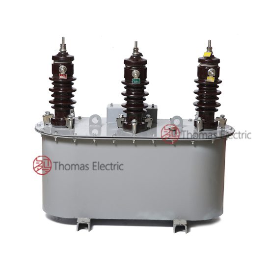
The JLS-20K is a single-phase, outdoor-rated cast-resin voltage transformer (VT) engineered for high-reliability operation in medium-voltage distribution networks operating at a nominal system voltage of 21 kV (IEC standard), corresponding to the domestic 20 kV system in China. Designed in strict compliance with IEC 61869-3 and GB/T 20840.3, this instrument transformer provides accurate voltage transformation for both metering and protective relaying functions in utility substations, industrial facilities, and renewable energy interconnection points.
Operating Principle of Cast-Resin Insulation
Cast-resin insulation in the JLS-20K employs vacuum pressure impregnation (VPI) technology using cycloaliphatic epoxy resin systems. This process fully encapsulates the primary and secondary windings along with the magnetic core, eliminating air voids that could lead to partial discharges under sustained electrical stress. The resin matrix provides superior dielectric strength—typically exceeding 20 kV/mm—and excellent tracking resistance, critical for outdoor exposure to pollution, moisture, and UV radiation. Unlike oil-filled units, the solid insulation eliminates fire hazards, environmental contamination risks, and the need for periodic oil sampling or gasket maintenance. The thermal class of the resin system is rated for continuous operation at 105°C ambient, with short-term overload capability up to 120°C without degradation of mechanical or electrical properties.
Advantages Over Oil-Immersed Designs
Compared to traditional oil-immersed voltage transformers, the JLS-20K offers significant operational and safety benefits. Its dry-type construction eliminates flammability concerns, making it suitable for indoor switchgear rooms and urban substations where fire codes restrict oil-filled equipment. Maintenance requirements are drastically reduced—no oil level checks, no desiccant replacement, and no risk of oil leakage contaminating soil or concrete foundations. The compact physical footprint allows for space-efficient mounting on poles, crossarms, or within ring-main units. Furthermore, the absence of liquid insulation ensures consistent performance across wide temperature ranges (-40°C to +40°C), with no viscosity-related delays in dielectric recovery after fault clearance. Electromagnetic compatibility is also enhanced due to the homogeneous dielectric environment, minimizing stray capacitance and improving transient response fidelity for digital relays.
Typical Applications Overview
The JLS-20K is primarily deployed in 21 kV (20 kV domestic) distribution networks where precise voltage measurement and reliable fault detection are essential. Common installations include 35/21 kV step-down substations feeding commercial districts, industrial plants with sensitive process loads, and grid-tied solar or wind farms requiring revenue-grade metering. Its robust design supports both single-phase and three-phase V-V or open-delta configurations for ground-fault detection. Secondary outputs typically feed multifunction meters, distance relays, synchrocheck devices, and SCADA RTUs. The transformer’s low burden rating and high accuracy class ensure minimal phase angle error—critical for power quality monitoring and directional overcurrent protection schemes in meshed networks.
Technical Specifications
The JLS-20K voltage transformer is engineered to deliver stable performance under defined service conditions while meeting stringent international accuracy and insulation requirements. All parameters align with IEC 61869-3:2011 and GB/T 20840.3-2013 standards.
Rated Electrical Parameters
The primary rated voltage is 21/√3 kV (phase-to-ground) for a 21 kV system, equivalent to 20/√3 kV in domestic Chinese networks. Standard secondary voltages include 100/√3 V, 100/3 V, or 110/√3 V, configurable based on customer relay and meter requirements. Accuracy classes are available in 0.2, 0.5, 1, and 3P/6P for metering and protection, respectively. Rated burdens range from 10 VA to 100 VA per secondary winding, with thermal short-time current ratings of 100 A for 1 second. The insulation level adheres to Um = 24 kV, with a lightning impulse withstand voltage of 125 kV peak and a power frequency wet withstand voltage of 50 kV rms for 1 minute. The maximum permissible temperature rise under rated load is 60 K above ambient, verified through standardized thermal tests per IEC 61869-3 Clause 7.4.
Environmental and Mechanical Ratings
Designed for outdoor installation, the JLS-20K operates reliably in ambient temperatures from -40°C to +40°C, with relative humidity up to 100% and condensation. It is rated for altitudes up to 1,000 meters above sea level; for installations above this, derating factors apply per IEC 60071-2. The housing features a hydrophobic, UV-stabilized cycloaliphatic epoxy surface with creepage distance ≥ 25 mm/kV (medium pollution severity, Class II per IEC 60815). Mounting is via standard M16 threaded inserts compatible with ANSI C57.12.28 or IEC 61869-1 brackets. Total weight is approximately 45 kg, with dimensions of 420 mm (height) × 280 mm (width) × 220 mm (depth). The secondary terminal box includes IP54-rated glands for cable entry and clearly marked polarity indicators (reducing polarity per IEC convention).
Magnetic Core and Winding Construction
The magnetic circuit utilizes grain-oriented electrical steel (GOES) laminations with a thickness of 0.27 mm, annealed to minimize hysteresis losses and core remanence. Core induction is maintained below 1.5 T at rated voltage to prevent saturation during transient overvoltages. Primary windings consist of enameled copper wire wound in layered sections with interlayer insulation of Nomex® paper, embedded within the epoxy matrix to suppress partial discharges (<5 pC at 1.2 × Ur). Secondary windings employ double-insulated magnet wire with reinforced terminations to withstand repeated plug-in cycles in test switches. All windings undergo vacuum drying prior to casting to achieve moisture content <0.1%, ensuring long-term dielectric integrity even in high-humidity coastal environments.
Typical Applications
The JLS-20K voltage transformer serves as a foundational component in modern medium-voltage infrastructure, enabling accurate energy billing, system protection, and grid stability monitoring.
Substation Secondary Metering
In 35/21 kV utility substations, the JLS-20K provides the voltage reference for revenue-class kWh meters and power quality analyzers. Configured in a V-V connection with two units, it delivers line-to-line voltages for three-phase metering without a neutral conductor. With an accuracy class of 0.2S, it meets MID (Measuring Instruments Directive) requirements for commercial billing, ensuring errors remain within ±0.2% from 1% to 120% of rated voltage. The low phase displacement (<10 minutes at 100% load) prevents reactive energy miscalculation in tariff structures that penalize poor power factor. Integration with AMI (Advanced Metering Infrastructure) systems is seamless due to the transformer’s stable ratio over time—drift is less than 0.05% annually under normal operating conditions.
Industrial Power Distribution
Large manufacturing facilities often deploy the JLS-20K on 20 kV busbars feeding motor control centers, arc furnaces, or data center UPS inputs. Here, it supplies voltage signals to multifunction protection relays (e.g., SEL-751 or Siemens 7SJ62) for undervoltage tripping, overvoltage alarm, and loss-of-potential detection. The 3P accuracy class ensures reliable operation during fault conditions, with ratio error held within ±3% at 5% to 100% of rated voltage. In harmonic-rich environments (THD >5%), the GOES core and distributed winding design limit resonant amplification, preventing false relay operations. Ground-fault detection in high-resistance grounded systems is achieved using an open-delta tertiary winding configuration, where the JLS-20K’s residual voltage output triggers ground-fault relays at 5 V or higher.
Renewable Energy Integration
Solar photovoltaic and wind farms connecting to 21 kV distribution feeders rely on the JLS-20K for grid synchronization and anti-islanding protection. During islanding events, voltage and frequency deviations must be detected within 2 seconds per IEEE 1547; the JLS-20K’s fast transient response (rise time <1 ms) ensures timely tripping. Its immunity to DC offset—critical during inverter faults—is verified by testing with superimposed 10% DC components without saturation. Revenue metering at the point of interconnection uses dual secondary windings: one for utility billing (0.2 class) and another for plant performance monitoring (0.5 class), reducing cabling costs and panel space.
Rural and Suburban Distribution Networks
In remote areas with limited maintenance access, the JLS-20K’s maintenance-free design is ideal for pole-mounted installations. It withstands frequent switching surges from capacitor bank operations and lightning-induced transients common in overhead line networks. The hydrophobic resin surface resists salt fog in coastal regions and cement dust in mining districts, maintaining insulation integrity without cleaning. For single-phase laterals serving residential clusters, it enables cost-effective single-phase metering with built-in fuse protection on the primary side (typically 0.5 A expulsion fuse). Its lightweight construction simplifies helicopter or bucket-truck installation, reducing outage durations during upgrades.
Compliance with International Standards
The JLS-20K is certified to both global and Chinese national standards, ensuring interoperability and regulatory acceptance across diverse markets.
IEC 61869-3 Compliance Details
IEC 61869-3 specifies performance, safety, and testing requirements for inductive voltage transformers. The JLS-20K meets all mandatory clauses, including accuracy limits under burden variations (Clause 5.3), temperature rise tests (Clause 7.4), and short-circuit withstand capability (Clause 7.6). Partial discharge measurements are conducted at 1.2 × Ur/√3 with levels maintained below 10 pC, well under the 20 pC limit for resin-cast units. Electromagnetic compatibility is validated per IEC 61000-4 series, ensuring immunity to 4 kV ESD and 1 MHz damped oscillatory waves. Marking includes IEC-standard symbols for polarity, accuracy class, and rated output, facilitating correct field wiring by technicians worldwide.
Alignment with GB/T 20840.3
GB/T 20840.3-2013 is the Chinese adoption of IEC 61869-3 with minor national deviations. The JLS-20K complies with all GB-specific requirements, including the use of 20 kV as the nominal system voltage (vs. 21 kV IEC) and Chinese character labeling on nameplates. Creepage distance requirements follow DL/T 729, mandating ≥31 mm/kV for heavy pollution zones (Class IV), which the JLS-20K exceeds with its 35 mm/kV design. Short-time current ratings are verified using Chinese grid fault current profiles, typically 16 kA for 2 seconds in 20 kV networks. Certification is issued by authorized Chinese bodies such as CEPREI or SGS-CSTC, with type test reports available upon request.
Key Differences Between IEC and Domestic Standards
While technically harmonized, practical differences exist. IEC 61869-3 uses 21 kV as the highest system voltage for equipment (Um), whereas GB/T 20840.3 references 20 kV as the nominal system voltage. This affects insulation coordination: IEC requires 125 kV LIWV for Um=24 kV, while GB may accept 110 kV for 20 kV systems in some legacy designs—but the JLS-20K meets the stricter IEC value universally. Accuracy verification under harmonic distortion is more explicitly defined in IEC, requiring testing with 3rd and 5th harmonics up to 5%; GB focuses on fundamental frequency performance. For export projects, dual marking (20/21 kV) on the nameplate resolves ambiguity during commissioning.
On-Site Testing Procedures
Field verification ensures the JLS-20K performs as specified after transportation and installation. All tests follow IEC 61869-3 Annex B and IEEE C57.13 guidelines.
Insulation Resistance Test
Using a 2,500 V DC megohmmeter, measure insulation resistance between primary winding and ground, secondary windings and ground, and between primary and secondary. Acceptance criteria: ≥1,000 MΩ at 20°C. Temperature correction is applied using RT2 = RT1 × 2(T1−T2)/10. Values below 500 MΩ indicate moisture ingress or resin cracking and require drying or replacement. This test is performed before energization and after any maintenance involving the terminal box.
Turns Ratio Test
Apply a low-voltage AC source (50–100 V) to the primary and measure secondary voltage with a calibrated RMS meter. Calculate ratio as Vp/Vs. Tolerance must be within ±0.1% of nameplate value for 0.2-class units, ±0.25% for 0.5-class, and ±1% for protection classes. Automated ratio testers (e.g., Omicron CT Analyzer) can perform this in under 2 minutes with automatic polarity detection. Deviations beyond tolerance suggest winding shorts or incorrect tap selection.
Polarity Verification
Confirm reducing polarity using the DC kick method: connect a 6–12 V battery momentarily to the primary (H1 to positive). Observe a momentary upscale deflection on a DC voltmeter connected to X1 (positive) and X2. Incorrect polarity causes negative deflection and must be corrected by swapping secondary leads. Polarity errors in three-phase banks cause vector group mismatches, leading to metering inaccuracies or relay misoperations.
Power Frequency Withstand Voltage Test
Apply 50 kV rms at 50 Hz between primary and ground (with secondaries shorted and grounded) for 1 minute. Use a calibrated test transformer with overcurrent trip set at 10 mA. No flashover or disruptive discharge is permitted. For routine maintenance, a 80% reduced test (40 kV for 1 min) is acceptable per IEC 60270. This verifies insulation integrity after exposure to switching surges or contamination.
Open-Circuit Characteristic Test
With secondary open, gradually increase primary voltage from 0 to 190% of rated (40 kV phase-to-ground). Record excitation current at 10%, 50%, 100%, 120%, and 190% Ur. At 100% Ur, excitation current should be ≤0.5% of rated primary current. A sharp current rise below 120% indicates core saturation due to mechanical damage or overheating. This test validates magnetic performance and detects inter-turn faults missed by ratio tests.
Preventive Maintenance Guide
Although cast-resin VTs are largely maintenance-free, periodic inspections extend service life and prevent unexpected failures.
Annual Visual and Functional Inspection
Inspect for surface cracks, tracking marks, or discoloration on the resin housing. Clean with mild detergent if salt or dust deposits exceed 0.1 mg/cm². Verify terminal tightness (torque: 2.5 N·m for M6 screws) and check for corrosion on grounding lugs. Perform insulation resistance and ratio tests annually in critical applications (e.g., revenue metering). Review historical test data for trends—insulation resistance declining by >20% year-over-year warrants further investigation.
Five-Year Comprehensive Maintenance
Every five years, conduct the full suite of on-site tests: insulation resistance, ratio, polarity, withstand voltage, and open-circuit characteristic. Additionally, inspect the primary fuse holder for oxidation and verify fuse rating matches system fault levels. If installed in high-pollution zones, measure surface conductivity using a saline solution per IEC 60507; values >100 µS indicate need for silicone grease application. Replace secondary terminal seals if hardened or cracked to maintain IP54 rating.
Fault Diagnosis and Troubleshooting
Common failure modes include secondary winding open-circuit (causing meter zero-readings), core saturation (leading to relay nuisance trips), and external flashover (from pollution). Diagnose by comparing phase voltages in a three-phase bank—if one unit reads 30% low, suspect internal turn-to-turn short. Thermal imaging can detect hot spots (>10 K above ambient) indicating poor connections. Never operate with secondary open under primary voltage—this induces dangerous overvoltages (>10 kV) that can rupture insulation. Always short secondaries before disconnecting loads.
Conclusion
The JLS-20K 21kV cast-resin voltage transformer represents a benchmark in reliability, accuracy, and compliance for modern medium-voltage systems. By leveraging advanced VPI epoxy resin technology and GOES silicon steel cores, it delivers stable ratio and phase angle performance across decades of service—typically 25 to 30 years under standard operating conditions. Its dual compliance with IEC 61869-3 and GB/T 20840.3 ensures seamless integration into both international and domestic grids, supporting applications from precision revenue metering to high-speed protection in complex industrial and renewable energy environments. The elimination of flammable liquids enhances safety in confined spaces, while the robust outdoor design withstands extreme climates without performance degradation. Field-proven testing and maintenance protocols further guarantee long-term operational integrity, minimizing lifecycle costs and maximizing grid uptime. For engineers specifying instrument transformers in 20/21 kV networks, the JLS-20K provides a technically superior, standards-compliant solution that balances performance, safety, and longevity.
Q1: Can the JLS-20K be used in a 22 kV system?
No. The JLS-20K is rated for Um = 24 kV, corresponding to 21 kV IEC or 20 kV domestic systems. Operation at 22 kV exceeds the continuous voltage rating and may cause accelerated aging or insulation failure.
Q2: What is the maximum altitude rating without derating?
The standard model is rated for ≤1,000 m. For 1,000–2,000 m, reduce rated voltage by 1% per 100 m above 1,000 m per IEC 60071-2.
Q3: Are multiple secondary windings available?
Yes. Configurations include one metering (0.2/0.5 class) and one protection (3P/6P) winding, or two identical metering windings for redundancy.
Q4: How is partial discharge measured in the field?
Field PD testing requires specialized equipment (e.g., OMICRON MPD 800). It is not routine but recommended after major faults or every 10 years in critical applications.
Q5: Is the JLS-20K suitable for indoor GIS applications?
While primarily outdoor-rated, it can be used indoors if ambient conditions meet specifications. However, SF6-insulated VTs are preferred for GIS due to space constraints.
Q6: What fuse rating is recommended for primary protection?
A 0.5 A, 24 kV expulsion fuse with I²t rating matched to the VT’s thermal withstand (typically 50 A²s) is standard.
Q7: Does it support digital output (e.g., IEC 61850-9-2)?
No. The JLS-20K is an analog inductive VT. For digital outputs, consider merging units paired with conventional VTs or standalone optical sensors.