Article Content
11kV Cast-Resin Voltage Transformer SZV-10R for Metering and Protection – IEC 61869-3 Standard
Introduction to the SZV-10R Voltage Transformer
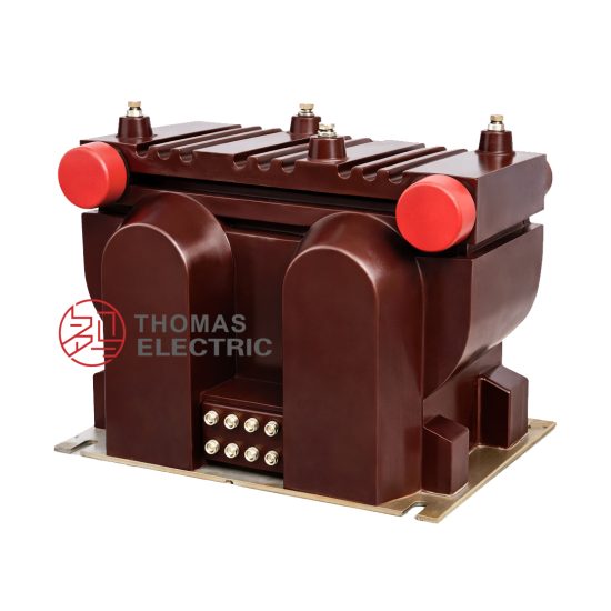
The SZV-10R is a precision-engineered, indoor-type electromagnetic voltage transformer (VT) rated for 11 kV (IEC standard), corresponding to 10 kV nominal system voltage in domestic applications. Designed specifically for medium-voltage distribution networks, this device provides accurate secondary voltage proportional to the primary system voltage, enabling reliable metering, protection, and control functions. Its construction leverages advanced cast-resin insulation technology, ensuring long-term dielectric integrity and mechanical robustness without the environmental and fire hazards associated with oil-filled alternatives.
Operating Principle and Cast-Resin Insulation Technology
The SZV-10R operates on the fundamental principle of electromagnetic induction. A primary winding connected across the 11 kV phase-to-ground or phase-to-phase circuit induces a scaled-down voltage in one or more secondary windings via a high-permeability magnetic core. The core is fabricated from grain-oriented electrical steel (GOES), which minimizes hysteresis and eddy current losses, thereby enhancing accuracy and thermal performance under continuous load.
Cast-resin insulation involves vacuum pressure impregnation (VPI) followed by epoxy resin casting under controlled conditions. This process fully encapsulates the windings and core, eliminating air voids that could lead to partial discharges. The resulting monolithic structure offers superior resistance to moisture ingress, pollution, and thermal cycling. Unlike oil-immersed VTs, the SZV-10R requires no oil containment, periodic oil sampling, or fire suppression systems, making it ideal for indoor substations, commercial buildings, and industrial facilities where space and safety are critical constraints.
Advantages Over Oil-Immersed Designs
Compared to traditional oil-filled voltage transformers, the SZV-10R delivers multiple operational and safety benefits. First, its dry-type construction eliminates flammability risks, aligning with modern fire safety codes such as IEC 60694 and NFPA 70. Second, the absence of liquid insulation removes maintenance tasks like oil level checks, dielectric strength testing, and leak repairs. Third, the compact footprint—enabled by high dielectric strength of epoxy resin (typically >20 kV/mm)—allows for direct mounting in metal-enclosed switchgear without external bushings.
Furthermore, cast-resin VTs exhibit excellent short-circuit withstand capability due to rigid mechanical support of windings. Thermal stability is maintained up to ambient temperatures of +40°C, with a maximum hotspot temperature rise of 60 K above ambient under rated load, per IEC 61869-3. These attributes translate into reduced lifecycle costs, enhanced reliability, and compliance with green infrastructure initiatives.
Typical Applications Overview
The SZV-10R is predominantly deployed in 10 kV (11 kV IEC) distribution systems requiring Class 0.2 or 0.5 accuracy for revenue metering or Class 3P/6P for protective relaying. Common installations include urban ring-main units (RMUs), prefabricated substations, industrial motor control centers (MCCs), and renewable energy interconnection points such as solar PV inverters or wind turbine step-up transformers. Its robust design supports operation in environments with relative humidity up to 95% and altitudes below 1,000 meters, extendable to 2,000 meters with derating.
Technical Specifications
The SZV-10R adheres strictly to IEC 61869-3 and GB/T 20840.3, ensuring global interoperability and performance consistency. Below is a detailed specification table followed by service condition parameters.
| Parameter | Value |
|---|---|
| Primary Voltage (IEC) | 11 kV (phase-to-ground) |
| Primary Voltage (Domestic) | 10 kV system nominal |
| Secondary Voltage(s) | 100 V, 100/√3 V, or dual outputs (e.g., 100/100 V) |
| Voltage Ratio | 11,000/100 V or 11,000/√3 : 100/√3 V |
| Accuracy Class | Metering: 0.2, 0.5; Protection: 3P, 6P |
| Rated Output (per burden class) | 10–100 VA (e.g., 30 VA at 0.2 class) |
| Insulation Level (LI/AC) | 75 kV lightning impulse / 28 kV power frequency (1 min) |
| Short-Time Withstand Current | Not applicable (VTs are not designed for fault current conduction) |
| Core Material | Grain-Oriented Electrical Steel (GOES), CRGO grade |
| Insulation System | Epoxy resin cast under VPI process, UL 94 V-0 flame rating |
| Polarity | Reduced polarity (standard per IEC 61869-3) |
Standard Service Conditions
The SZV-10R is rated for indoor use under normal service conditions as defined in IEC 61869-3 Clause 5. The ambient temperature range is –5°C to +40°C, with a 24-hour average not exceeding +35°C. Relative humidity may reach 95% at +25°C without condensation. Installation altitude is limited to 1,000 meters above sea level; for altitudes between 1,001 m and 2,000 m, the power frequency withstand voltage must be reduced by 1% per 100 m above 1,000 m.
Environmental contaminants such as dust, salt, or chemical vapors should not exceed pollution degree 2 per IEC 60664-1. In harsher environments (e.g., coastal or industrial zones), additional creepage distance or conformal coating may be required—though the inherent hydrophobicity of cured epoxy resin provides baseline resistance to surface tracking.
Electrical Performance Tolerances
Voltage error and phase displacement must comply with IEC 61869-3 Table 2. For a 0.2-class VT at 80–120% of rated voltage and 25–100% of rated burden, voltage error shall not exceed ±0.2%, and phase displacement shall be ≤±10 minutes. At 100% voltage and 100% burden, typical measured values for the SZV-10R are +0.08% error and +4′ phase shift, well within tolerance.
Thermal performance is validated through temperature-rise tests per IEC 61869-3 Annex B. Under continuous operation at 1.2× rated voltage and 100% burden, the winding temperature rise does not exceed 60 K, ensuring insulation life expectancy of 25–30 years based on Arrhenius aging models.
Typical Applications
Substation Secondary Metering
In utility-owned 10 kV/0.4 kV distribution substations, the SZV-10R provides the reference voltage signal for kWh meters, demand recorders, and power quality analyzers. Its 0.2-class accuracy ensures compliance with regulatory billing requirements (e.g., EN 50470-3). The transformer is typically installed on the 10 kV busbar inside metal-clad switchgear, with secondary leads routed to a dedicated metering compartment. Dual secondary windings allow simultaneous connection to revenue metering (0.2 class) and SCADA telemetry (0.5 class), eliminating cross-interference.
Industrial Power Distribution Systems
Large manufacturing plants often operate internal 10 kV networks to minimize transmission losses. Here, the SZV-10R feeds voltage inputs to protective relays (e.g., over/under-voltage, directional earth fault) and energy management systems. For example, in a steel mill with arc furnaces, the VT’s immunity to harmonic distortion—thanks to low core loss and linear B-H curve of GOES—ensures stable relay operation even under non-sinusoidal conditions. The cast-resin body withstands mechanical vibrations from nearby equipment without degradation.
Renewable Energy Integration
Solar farms and wind parks frequently connect to the grid via 10 kV collection systems. The SZV-10R monitors point-of-interconnection voltage for anti-islanding protection, reactive power control, and grid code compliance (e.g., IEEE 1547 or GB/T 19964). Its fast response time (<20 ms) and low remanence enable accurate detection of voltage sags during cloud transients or gust events. Moreover, the absence of oil simplifies permitting in environmentally sensitive areas.
Rural and Suburban Distribution Networks
In remote or semi-urban areas, compact secondary substations equipped with RMUs rely on the SZV-10R for local voltage monitoring. These units often lack climate control, making the VT’s wide operating temperature range essential. The transformer’s maintenance-free nature reduces the need for frequent site visits—a critical advantage in regions with limited technical personnel. Additionally, its lightweight design (typically 45–60 kg) facilitates manual handling during pole-mounted or pad-mounted installations.
Commercial Building Infrastructure
High-rise office complexes and data centers use 10 kV feeders for efficient power delivery. The SZV-10R supplies voltage signals to building automation systems (BAS) and uninterruptible power supply (UPS) synchronization circuits. Fire safety regulations in such occupancies prohibit flammable insulation, making cast-resin VTs the only viable option. The SZV-10R’s low partial discharge levels (<5 pC at 1.2× Ur) also prevent electromagnetic interference with sensitive IT equipment.
Compliance with International Standards
IEC 61869-3 Certification Requirements
IEC 61869-3:2011 specifies performance, safety, and test requirements for inductive voltage transformers. The SZV-10R undergoes type tests including temperature rise, short-circuit withstand (for auxiliary windings), insulation coordination, and accuracy verification across burden and voltage ranges. Routine tests—performed on every unit—include power frequency withstand (28 kV, 1 min), partial discharge measurement (<10 pC at 1.2× Ur/√3), and polarity check. The manufacturer must provide a test report traceable to an ISO/IEC 17025-accredited laboratory.
Alignment with GB/T 20840.3
China’s national standard GB/T 20840.3 mirrors IEC 61869-3 but includes localized requirements such as mandatory seismic testing (Class II per GB/T 13540) for earthquake-prone regions and stricter partial discharge limits (<3 pC at factory test). The SZV-10R is certified by CQC (China Quality Certification Center) and bears the CCC mark, confirming compliance with both GB/T 20840.3 and IEC 61869-3. Notably, GB/T allows 10 kV as the rated voltage designation, whereas IEC uses 11 kV—this reflects the same physical device rated for 12 kV maximum system voltage.
Key Differences Between IEC and Domestic Standards
While IEC 61869-3 focuses on functional performance, GB/T 20840.3 emphasizes environmental resilience and local grid compatibility. For instance, GB/T mandates a 1-minute power frequency test at 30 kV (vs. 28 kV in IEC) and requires verification of accuracy at 190% of rated voltage for ferroresonance immunity—a common issue in Chinese rural grids with long overhead lines. Additionally, GB/T specifies terminal marking in Chinese characters alongside IEC symbols (e.g., “A-X” and “a-x”). Despite these nuances, the SZV-10R’s design envelope accommodates both standards without modification, facilitating export and domestic deployment.
On-Site Testing Procedures
Insulation Resistance Test
Conducted using a 2,500 V DC megohmmeter per IEC 60270. Measure resistance between primary winding and ground, secondary windings and ground, and primary-to-secondary. Acceptance criterion: ≥1,000 MΩ at 20°C. Correct for temperature using RT2 = RT1 × 2(T1–T2)/10. Low readings indicate moisture ingress or resin cracking—requiring drying or replacement.
Turns Ratio Test
Apply 100–200 V AC to the primary and measure secondary voltage. Calculate ratio as Vp/Vs. Compare to nameplate value (e.g., 110:1). Tolerance per IEC 61869-3: ±0.2% for 0.2-class VTs. Use a dedicated turns ratio tester (e.g., Omicron TTR300) for accuracy. Deviations >0.5% suggest inter-turn faults or incorrect tap selection.
Polarity Verification
Connect a 6–12 V battery across primary terminals (A to +, X to –). Momentarily close the circuit and observe a DC voltmeter connected to secondary (a to +, x to –). A positive kick confirms reduced polarity. Incorrect polarity causes 180° phase reversal, leading to metering errors or relay misoperation. This test is mandatory after transportation or reconnection.
Power Frequency Withstand Voltage Test
Apply 28 kV RMS (IEC) or 30 kV RMS (GB) at 50 Hz between primary and grounded secondary/core for 1 minute. Use a calibrated test transformer with overcurrent protection. No flashover or breakdown is permitted. This test validates insulation integrity post-installation but should be avoided if partial discharge history is available, as repeated high-voltage stress accelerates aging.
Open-Circuit Characteristic Test
With secondaries open, gradually increase primary voltage from 20% to 150% of rated (16.5 kV). Record excitation current. A sharp current rise above 120% indicates core saturation or turn-to-turn shorts. The knee point should exceed 130% of Ur. This test is critical for detecting manufacturing defects or damage during shipping.
Preventive Maintenance Guide
Periodic Visual and Functional Inspection
Annual inspections should verify: (1) clean, crack-free resin surface; (2) tight terminal connections (torque: 15 N·m for M8 bolts); (3) absence of corona discharge signs (ozone smell, white powder); (4) correct secondary burden (≤rated VA). Use thermal imaging to detect hotspots (>10 K above ambient indicates overload or poor contact). Document findings in a maintenance log.
Long-Term Maintenance Schedule
Every 5 years, perform insulation resistance, turns ratio, and open-circuit tests. Replace surge arresters connected to the VT primary if leakage current exceeds 0.5 mA. After any system fault involving voltage transients (e.g., lightning strike), conduct partial discharge measurement—if >20 pC at 1.2× Ur, investigate further. The SZV-10R’s expected service life is 25–30 years with proper maintenance; end-of-life indicators include persistent accuracy drift or visible resin degradation.
| Interval | Action |
|---|---|
| Annually | Visual inspection, thermal scan, terminal torque check |
| Every 5 Years | Insulation resistance, ratio test, open-circuit test |
| After Major Fault | Partial discharge test, accuracy verification |
| End of Life (25+ Years) | Full re-certification or replacement |
Conclusion
The SZV-10R 11 kV cast-resin voltage transformer represents a benchmark in reliability, accuracy, and safety for medium-voltage applications. By leveraging vacuum-pressure-impregnated epoxy resin and GOES core technology, it achieves superior dielectric strength, thermal stability, and environmental resilience compared to legacy oil-filled designs. Compliance with both IEC 61869-3 and GB/T 20840.3 ensures seamless integration into global power systems—from urban substations to remote renewable sites. Its maintenance-free operation, compact form factor, and 25–30 year service life significantly reduce total cost of ownership while supporting stringent metering and protection requirements. When installed and tested according to the procedures outlined in this guide, the SZV-10R delivers decades of trouble-free performance, making it an optimal choice for modern 10 kV distribution infrastructure seeking future-proof, sustainable solutions.
Frequently Asked Questions (FAQ)
Q1: Can the SZV-10R be used in outdoor switchgear?
A: No. The SZV-10R is rated for indoor use only (IP00 enclosure). For outdoor applications, select a weatherproof model with IP54 rating and UV-stabilized resin.
Q2: What is the maximum allowable secondary burden?
A: The burden must not exceed the rated output (e.g., 30 VA for 0.2 class). Exceeding this causes accuracy degradation and potential overheating. Always verify connected load impedance.
Q3: Is a power frequency withstand test required after installation?
A: Only if specified by the utility or after major modifications. Repeated high-voltage testing accelerates insulation aging; routine maintenance relies on insulation resistance and partial discharge tests.
Q4: How do I detect ferroresonance in SZV-10R installations?
A: Ferroresonance manifests as abnormal humming, voltage distortion, or overheating. Mitigate by using damped VTs, resistive loading, or avoiding single-pole switching on unloaded cables.
Q5: Can I parallel two SZV-10R units for redundancy?
A: Not recommended. VT secondaries must never be paralleled unless specifically designed for it, due to circulating currents causing accuracy errors and overheating.
Q6: What causes accuracy drift over time?
A: Primary causes include core aging (remanence increase), moisture ingress (resin microcracks), or loose windings. Regular open-circuit and ratio tests identify these issues early.