Article Content
For Substation Metering & Protection: SZW-10K 11kV Cast-Resin Voltage Transformer per IEC 61869-3
Introduction to the SZW-10K Voltage Transformer
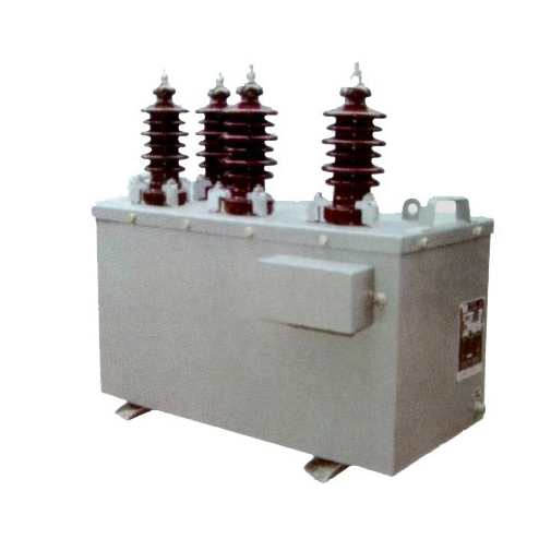
The SZW-10K is a single-phase, indoor/outdoor-rated cast-resin voltage transformer (VT) engineered for reliable operation in 11kV medium-voltage distribution networks. Designed in accordance with IEC 61869-3 and GB/T 20840.3, it provides precise voltage transformation from a nominal system voltage of 11kV (IEC standard) or 10kV (domestic Chinese grid equivalent) down to standardized secondary outputs of 100 V or 110 V. This enables safe interfacing with protective relays, revenue-class meters, SCADA systems, and power quality analyzers.
Operating Principle of Cast-Resin Insulation
Cast-resin insulation in the SZW-10K employs vacuum pressure impregnation (VPI) technology using cycloaliphatic epoxy resin. The primary and secondary windings—wound on high-permeability GOES (grain-oriented electrical steel) cores—are fully encapsulated under vacuum to eliminate air voids and moisture ingress. This monolithic structure provides superior dielectric strength, tracking resistance, and mechanical stability compared to traditional oil-filled or dry-wound designs. The resin’s thermal class is F (155°C), supporting continuous operation at ambient temperatures up to 40°C with a 10K hotspot allowance. Partial discharge levels are maintained below 10 pC at 1.2 × Um/√3 (7.6 kV), ensuring long-term insulation integrity even under transient overvoltages.
Advantages Over Oil-Immersed Designs
Unlike oil-immersed VTs, the SZW-10K eliminates fire hazards, environmental contamination risks, and maintenance-intensive oil sampling. Its solid insulation requires no periodic oil testing, degassing, or leakage monitoring. The compact footprint (typically 380 mm height × 220 mm base) allows direct mounting on switchgear busbars without external tanks. Additionally, cast-resin construction offers higher seismic resilience (up to 0.5g) and immunity to humidity-induced degradation—critical for coastal or tropical installations. The absence of flammable materials also permits deployment in confined urban substations where fire codes restrict oil-filled equipment.
Typical Applications Overview
The SZW-10K is deployed across utility substations, industrial plants, renewable energy farms, and commercial complexes requiring accurate voltage measurement for billing, protection coordination, or harmonic monitoring. Its dual secondary windings (e.g., 0.5/3P accuracy classes) support simultaneous metering and protection functions. Common configurations include single-pole connection to 11kV busbars or three-unit star-connected banks for three-phase systems. The transformer’s robust design ensures stable performance under unbalanced loading, ferroresonance conditions, and frequent switching transients typical in modern distribution grids.
Technical Specifications
The SZW-10K adheres to stringent electrical and environmental parameters defined by international and domestic standards. Key specifications ensure compatibility with global substation architectures while maintaining metrological precision.
Rated Electrical Parameters
Primary rated voltage: 11 kV (Um = 12 kV). Secondary voltages: 100 V or 110 V (standardized per IEC 61869-3). Standard voltage ratios include 11000/√3 : 100/√3 V and 11000/√3 : 110/√3 V for phase-to-ground applications. Accuracy classes: 0.2, 0.5 for metering; 3P or 6P for protection. Rated outputs: 30 VA, 50 VA, or 100 VA per secondary winding. Burden must not exceed rated output to maintain declared accuracy. Insulation level: Lightning impulse withstand voltage (LIWV) = 75 kV peak; Power frequency withstand voltage (PFWD) = 28 kV rms for 1 minute. Short-time thermal current rating: 100 A for 1 second.
Environmental and Mechanical Ratings
Service conditions per IEC 61869-3: Ambient temperature range: –25°C to +40°C (with derating above 40°C). Relative humidity: ≤95% non-condensing. Altitude: ≤1000 m above sea level (for altitudes >1000 m, voltage withstand values must be corrected per IEC 60071-2). Pollution degree: III (creepage distance ≥25 mm/kV). Degree of protection: IP00 (indoor) or IP23 (outdoor with optional weather shield). Mounting: Vertical or horizontal via M12 threaded studs. Weight: Approximately 28 kg. Core material: CRGO silicon steel laminations (losses ≤1.2 W/kg at 1.7 T, 50 Hz).
Accuracy and Performance Characteristics
Voltage error at rated burden and 80–120% of rated voltage must remain within ±0.2% for class 0.2 and ±0.5% for class 0.5. Phase displacement is limited to ±10 minutes for class 0.2 and ±20 minutes for class 0.5. Under no-load conditions, the open-circuit secondary voltage deviation is <0.1%. Temperature rise at rated load: ≤60 K for windings (measured by resistance method). Residual voltage ratio (RVR) for protection windings complies with IEC 61869-3 Annex C, ensuring reliable operation during earth-fault conditions in resonant-grounded systems.
Typical Applications
The SZW-10K serves diverse roles in modern power infrastructure, leveraging its metrological accuracy and rugged construction.
Substation Secondary Metering
In 11kV primary substations, the SZW-10K feeds revenue-grade kWh meters and demand recorders. Its 0.2 or 0.5 accuracy class ensures compliance with regulatory billing requirements (e.g., China’s DL/T 448). Dual secondary windings allow one circuit for utility metering and another for internal plant monitoring. For example, a 11000/√3 : 100/√3 V ratio with 30 VA burden supports Class 0.5 meters over a 50-meter cable run without exceeding composite error limits. Proper burden matching prevents saturation during fault conditions, preserving waveform fidelity for tariff calculations.
Industrial Power Distribution
Heavy industries (e.g., steel mills, chemical plants) use the SZW-10K for motor protection, capacitor bank control, and arc-flash mitigation. Protection-class windings (3P) interface with overvoltage relays (e.g., Siemens 7SJ62) to detect ground faults in high-resistance grounded systems. The VT’s low leakage inductance minimizes transient overshoot during breaker operations, preventing nuisance tripping. In facilities with variable-frequency drives, the SZW-10K’s low harmonic distortion (<0.5% THD at rated load) ensures accurate harmonic monitoring up to the 13th order.
Renewable Energy Integration
Solar and wind farms deploy SZW-10K units at collector substations to monitor grid voltage for anti-islanding protection and reactive power control. During cloud transients or wind gusts, rapid voltage fluctuations require VTs with fast response times—achieved here via low magnetizing current (<0.5% of rated primary current). The cast-resin body resists UV degradation and thermal cycling, critical for desert or offshore sites. Compliance with IEC 61869-3 ensures interoperability with IEC 61850-compliant bay controllers.
Rural and Suburban Distribution Networks
In remote areas with long feeders, the SZW-10K enables voltage regulation via automatic tap changers and capacitor switching. Its high insulation margin accommodates temporary overvoltages from load rejection. For pole-mounted installations, the optional IP23 shroud protects terminals from rain and dust. Utilities leverage its 25+ year service life to reduce lifecycle costs in hard-to-access locations. Field data shows <0.1% annual failure rate when operated within rated parameters.
Compliance with International Standards
The SZW-10K is certified to both global and Chinese national standards, ensuring universal acceptance and interoperability.
IEC 61869-3 Certification Requirements
IEC 61869-3 governs instrument transformers for frequencies 50/60 Hz and voltages >1 kV. The SZW-10K undergoes type tests including temperature rise, short-circuit withstand, impulse voltage, and accuracy verification across burden ranges. Routine tests per clause 10 include turns ratio, polarity, and power frequency withstand. Special tests (e.g., partial discharge, capacitance/tan δ) confirm insulation quality. Certification requires third-party lab validation (e.g., KEMA, CESI) with test reports traceable to SI units. Marking includes “IEC 61869-3” and accuracy class per IEC 60044-2 legacy alignment.
GB/T 20840.3 Alignment and Differences
GB/T 20840.3 mirrors IEC 61869-3 but includes China-specific provisions: mandatory 10kV system voltage reference (vs. 11kV IEC), stricter creepage distances for polluted environments (≥31 mm/kV in Zone IV), and additional seismic testing per GB/T 13540. While IEC permits 110 V secondary outputs, GB/T emphasizes 100 V as default. Accuracy class definitions are identical, but GB/T requires extended thermal stability testing at 1.2 × Un for 8 hours. Despite these nuances, the SZW-10K meets both standards through dual-certified design documentation.
Testing and Certification Documentation
Each SZW-10K unit ships with a test certificate listing individual results for ratio error, phase displacement, insulation resistance (>10 GΩ at 2500 V DC), and partial discharge. Type test reports cover full compliance with IEC 61869-3 clauses 7–9. For Chinese projects, a GB/T 20840.3 conformity declaration is provided, including CCC certification if required. Calibration certificates traceable to NIM (National Institute of Metrology, China) or PTB (Germany) support metrological audits.
On-Site Testing Procedures
Post-installation and periodic field tests validate SZW-10K performance and safety.
Insulation Resistance Test
Perform with a 2500 V DC megohmmeter between primary winding and ground, and between secondary windings and ground. Acceptance criterion: ≥10 GΩ at 20°C. Correct for temperature using RT2 = RT1 × 2(T1–T2)/10. Low readings indicate moisture ingress or resin cracking. Always discharge windings after testing. For outdoor units, clean terminals with isopropyl alcohol before measurement to avoid surface leakage errors.
Turns Ratio Test
Apply 100–200 V AC to the primary and measure secondary voltage. Calculate ratio = Vp/Vs. Compare to nameplate value (e.g., 63.51 for 11000/√3 : 100/√3). Tolerance: ±0.2% for metering class, ±0.5% for protection class. Use a dedicated ratio tester (e.g., Omicron CT Analyzer) for automated comparison. Deviations >1% suggest inter-turn shorts or winding damage.
Polarity Verification
Confirm reducing polarity per IEC 61869-3 Figure 3. Apply low-voltage DC pulse to primary; observe secondary voltage polarity with an oscilloscope. Positive primary terminal should yield positive secondary instantaneous voltage. Incorrect polarity causes relay misoperation—e.g., reverse power flow detection in directional overcurrent schemes. Label terminals “A” (HV) and “a” (LV) consistently.
Power Frequency Withstand Voltage Test
Apply 28 kV rms (50 Hz) between primary and ground for 1 minute. Secondary windings must be short-circuited and grounded. Monitor for flashover or excessive current (>5 mA). This test validates insulation integrity after transport or installation stress. Never perform if ambient humidity >80%—condensation risks false failures. Use a calibrated HV test set with overcurrent trip.
Open-Circuit Characteristic Test
Gradually increase primary voltage from 0 to 1.5 × Un (16.5 kV) while measuring secondary voltage and excitation current. Plot Vs vs. Iexc. Knee point should exceed 1.3 × Un. Excessive magnetizing current (>2% of rated) indicates core saturation or degraded lamination insulation. This test detects ferroresonance susceptibility in isolated-neutral systems.
Preventive Maintenance Guide
Proactive maintenance extends service life and prevents unplanned outages.
Annual Visual and Functional Inspection
Check for resin cracks, terminal corrosion, or tracking marks. Verify torque on mounting bolts (25 N·m for M12). Measure secondary voltage under load—deviation >1% from baseline warrants further testing. Clean insulator surfaces with non-abrasive detergent. Inspect grounding continuity (<0.1 Ω resistance). Document findings in asset management software.
Five-Year Comprehensive Maintenance
Repeat all on-site tests (Sections 5.1–5.5). Perform thermographic scan during peak load—hotspots >10K above ambient indicate internal faults. Test secondary circuit burden with a precision load box; replace degraded cables causing excessive voltage drop. Recalibrate if ratio error exceeds half the accuracy class limit. Update test records in the transformer’s lifetime dossier.
Fault Diagnosis and Troubleshooting
Common issues: Blown secondary fuses (check for short circuits), erratic meter readings (verify burden and polarity), or overheating (measure excitation current). If insulation resistance drops below 1 GΩ, bake the unit at 80°C for 24 hours in a controlled oven—only if no physical damage exists. Persistent partial discharge >20 pC requires replacement. Never operate with open secondary circuits—this induces dangerous overvoltages.
| Maintenance Interval | Activities |
|---|---|
| Annual | Visual inspection, terminal torque check, secondary voltage verification |
| 5 Years | Full electrical testing, thermography, burden validation, recalibration |
| After Fault Events | Insulation resistance, ratio test, open-circuit characteristic |
Conclusion
The SZW-10K 11kV cast-resin voltage transformer represents a benchmark in reliability, accuracy, and compliance for medium-voltage applications. Its epoxy-resin encapsulation eliminates the operational hazards and maintenance burdens associated with oil-filled alternatives, while delivering metrological performance that meets stringent IEC 61869-3 and GB/T 20840.3 requirements. Engineered with GOES cores and optimized winding geometry, it maintains ratio error within ±0.2% under varying load and temperature conditions—critical for revenue metering and sensitive protection schemes. The transformer’s robust insulation system, validated by lightning impulse and power frequency withstand tests, ensures decades of service even in harsh environments. With a design life of 25–30 years and minimal preventive maintenance needs, the SZW-10K reduces total cost of ownership while enhancing grid safety and measurement integrity. Its dual-standard certification facilitates deployment across international projects, from urban substations to remote renewable sites, making it a versatile solution for modern power systems demanding precision, durability, and regulatory compliance.
Frequently Asked Questions (FAQ)
Q1: Can the SZW-10K be used on a 10kV system?
Yes. While rated for 11kV per IEC standards, the SZW-10K is fully compatible with 10kV domestic systems (Un = 10 kV, Um = 11.5 kV). Ensure the voltage ratio matches your secondary requirements (e.g., 10000/√3 : 100/√3 V).
Q2: What is the maximum allowable secondary burden?
The burden must not exceed the rated output (e.g., 50 VA). Exceeding this causes increased ratio error and phase displacement. For Class 0.5, total burden (cable + device) should be ≤45 VA to maintain accuracy.
Q3: How often should insulation resistance be tested?
Annually during routine inspection. After any fault event (e.g., lightning strike), test immediately. Acceptable value: ≥10 GΩ at 25°C. Values below 1 GΩ require investigation.
Q4: Is the SZW-10K suitable for outdoor installation?
Yes, with an optional IP23 weather shield. Without shielding, it is rated for indoor use only (IP00). Ensure terminals are protected from direct rainfall and dust accumulation.
Q5: What causes ferroresonance in VTs, and how is the SZW-10K protected?
Ferroresonance occurs when VT magnetizing reactance resonates with system capacitance during single-pole switching. The SZW-10K mitigates this via core design limiting saturation and damping resistors (if specified). Avoid open-delta connections without supervision relays.
Q6: Can I parallel two SZW-10K secondaries for higher burden capacity?
No. Paralleling VT secondaries is prohibited—it creates circulating currents and measurement errors. Use a single VT with adequate rated output or separate windings for independent circuits.