Article Content
IEC 61869-2 Certified 11kV Current Transformer ZW-10 for Metering & Protection Applications
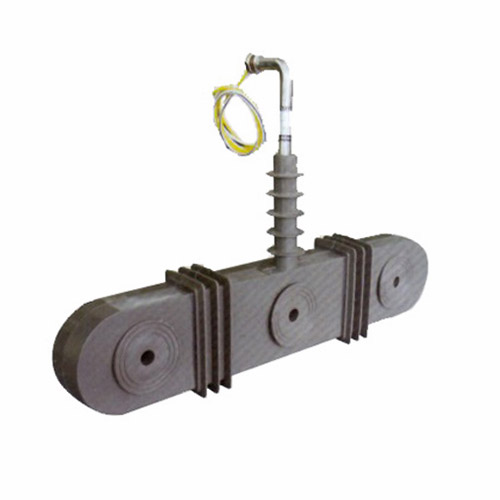
Introduction to the ZW-10 Current Transformer
The ZW-10 is a dry-type, cast-resin insulated current transformer (CT) engineered for reliable operation in 11kV (IEC standard) or 10kV (domestic Chinese system) medium-voltage networks. Designed in strict accordance with IEC 61869-2 and GB/T 20840.2, it serves critical roles in both protective relaying and revenue-grade metering within substations, industrial facilities, and renewable energy interconnection points. Unlike traditional oil-immersed CTs, the ZW-10 leverages advanced vacuum pressure impregnation (VPI) epoxy resin technology to encapsulate its magnetic core and windings, eliminating fire hazards, environmental leakage risks, and maintenance-intensive fluid management.
Operating Principle of Cast-Resin Insulation
Cast-resin insulation in the ZW-10 utilizes a two-component cycloaliphatic epoxy resin system cured under vacuum and pressure. This process ensures complete void-free encapsulation of the GOES (grain-oriented electrical steel) core and copper secondary windings. The absence of air pockets prevents partial discharge inception even under transient overvoltages, a critical requirement per IEC 61869-2 Clause 7.3. The resin’s high dielectric strength (≥20 kV/mm) and thermal conductivity (0.8–1.2 W/m·K) enable stable performance across -40°C to +40°C ambient temperatures. Additionally, the monolithic structure provides mechanical robustness against seismic loads (up to 0.5g) and short-circuit electromagnetic forces, making it suitable for both indoor switchgear and outdoor pole-mounted installations.
Advantages Over Oil-Immersed Designs
The ZW-10 eliminates the operational drawbacks of oil-filled CTs: no risk of flammable oil leakage, no need for periodic oil sampling or degassing, and immunity to moisture ingress through gaskets or breathers. Its dry-type construction reduces lifecycle costs by 30–40% due to minimal preventive maintenance. Furthermore, the compact footprint—enabled by higher insulation efficiency—allows integration into space-constrained ring main units (RMUs) and metal-clad switchgear. Environmental compliance is enhanced as the unit contains no PCBs or hazardous fluids, aligning with RoHS and IEC 62430 eco-design directives. Fire safety certification per IEC 60695-11-10 (glow-wire test at 960°C) further validates its suitability for urban substations near public infrastructure.
Typical Applications Overview
The ZW-10 is deployed across diverse power systems requiring accurate current transformation with long-term reliability. Primary use cases include feeder protection in 11kV distribution substations, where its 5P20 accuracy class ensures correct operation during 20× rated fault currents. In commercial buildings and data centers, it supports Class 0.5S metering for billing compliance under IEC 62053-22. Renewable integration projects—such as solar farms feeding into 10kV/11kV grids—rely on its low phase error (<±10 arcmin at 1.2×In) for synchrophasor measurements. Rural electrification schemes benefit from its resistance to humidity and dust, while industrial plants utilize its high thermal withstand capability (1s short-time current up to 31.5 kA).
Technical Specifications
The ZW-10 is engineered to meet stringent electrical and environmental performance criteria defined by international and domestic standards. Below is a comprehensive specification table followed by detailed service condition parameters.
| Parameter | Value |
|---|---|
| Rated Voltage (Ur) | 11 kV (IEC), 10 kV (GB) |
| System Frequency | 50/60 Hz |
| Primary Current (Ip) | 50 A to 3150 A (standard ratios) |
| Secondary Current (Is) | 1 A or 5 A |
| Accuracy Class (Metering) | 0.2S, 0.5S per IEC 61869-2 |
| Accuracy Class (Protection) | 5P10, 5P20, 10P10 per IEC 61869-2 |
| Rated Burden | 2.5 VA to 30 VA (at cosφ = 0.8) |
| Insulation Level (LI/AC) | 75 kV / 28 kV (1 min, 50 Hz) |
| Short-Time Thermal Current | 20–31.5 kA for 1 s |
| Dynamic Withstand Current | 50–80 kA peak |
| Core Material | GOES (Grain-Oriented Electrical Steel), M4 grade |
| Insulation System | VPI Epoxy Resin, UL 1446 Class F (155°C) |
| Ambient Temperature Range | -40°C to +40°C |
| Relative Humidity | Up to 100% (condensing) |
| Maximum Altitude | 1000 m above sea level (derating required >1000 m) |
Standard Service Conditions
The ZW-10 operates reliably under IEC 60060-1 defined standard atmospheric conditions: ambient temperature between -40°C and +40°C, daily average not exceeding +35°C. Relative humidity may reach 100%, including condensation, without degradation—critical for coastal or tropical installations. At altitudes above 1000 m, the dielectric strength decreases by approximately 1% per 100 m; thus, for 2000 m sites, the power frequency withstand voltage must be reduced to 25.2 kV (90% of 28 kV). The unit is rated for continuous operation at 1.2×Ur under unbalanced load conditions, with thermal stability verified per IEC 61869-2 Annex B temperature rise tests (max ΔT ≤ 60 K for windings).
Accuracy and Burden Characteristics
Metering variants (0.2S/0.5S) maintain composite error within ±0.2% and ±0.5% respectively at 1% to 120% of rated current (In), essential for AMI (Advanced Metering Infrastructure) compliance. Protection classes (5P20) guarantee ≤5% ratio error and ≤10% phase displacement at 20×In with rated burden. Burden tolerance is ±10% of nominal value; exceeding this may cause saturation during faults. For example, a ZW-10 rated 600/5A, 5P20, 15 VA must drive a total loop impedance ≤0.6 Ω (including relay, wiring, and contact resistance). Core remanence is limited to ≤10% of saturation flux density to prevent maloperation after DC-offset fault clearing.
Typical Applications
The ZW-10’s robust design enables deployment across multiple power system segments requiring precision, safety, and longevity.
Substation Secondary Metering
In 11kV primary substations, the ZW-10 provides Class 0.2S current signals to revenue meters compliant with IEC 62053-22. Its low phase error ensures accurate kWh and kvarh measurement even under distorted waveforms (THD ≤15%). For instance, in a 10 MVA urban substation feeding commercial loads, three ZW-10 units (1000/5A, 0.2S, 10 VA) interface with a multi-tariff meter, enabling time-of-use billing with <0.3% uncertainty. The cast-resin housing resists tracking from pollution, critical in industrial zones with airborne conductive contaminants.
Industrial Power Distribution
Heavy industries—such as steel mills or chemical plants—utilize ZW-10 CTs for motor protection and harmonic monitoring. A typical 630 kW induction motor circuit employs a 400/1A, 5P20, 5 VA unit feeding a digital relay (e.g., SEL-751). The CT’s high saturation point (Vk ≥ 200 V) prevents false tripping during motor start-up inrush (6–8×In). In arc furnace applications with severe harmonics, the GOES core’s low hysteresis loss minimizes heating, extending service life beyond 25 years.
Renewable Energy Integration
Solar photovoltaic (PV) farms connecting to 10kV/11kV grids require CTs with bidirectional current handling and low remanence. The ZW-10 meets these needs: its symmetrical core design supports reverse power flow during grid-support modes (e.g., reactive power injection), while post-fault remanence <8% ensures rapid reset for subsequent events. In a 20 MW solar plant, ZW-10 units (1250/5A, 0.5S) feed SCADA systems for real-time generation reporting and anti-islanding protection coordination.
Rural and Suburban Distribution Networks
Pole-mounted ZW-10 CTs are ideal for rural feeders due to their weather resistance and vandal-proof construction. Installed on 11kV overhead lines, they enable remote fault location via traveling-wave detection. For example, a 50 km rural circuit uses ZW-10 (200/5A, 10P10) at sectionalizing points to isolate single-phase-to-ground faults within 100 ms. The IP54-rated terminal box protects secondary connections from rain and dust, eliminating corrosion-related measurement drift common in open-frame CTs.
Compliance with International Standards
The ZW-10 is certified to IEC 61869-2:2012 (“Instrument transformers – Part 2: Additional requirements for current transformers”) and fully aligned with China’s GB/T 20840.2-2014, ensuring global interoperability and regulatory acceptance.
IEC 61869-2 Compliance Details
Key IEC 61869-2 requirements met include: temperature rise limits (Clause 6.3), short-circuit withstand (Clause 6.5), accuracy verification under harmonic distortion (Annex D), and partial discharge levels <10 pC at 1.2×Ur/√3 (Clause 7.4). Type tests performed by accredited labs include power frequency withstand (28 kV, 1 min), lightning impulse (75 kV, 1.2/50 μs), and thermal stability (1.1×In for 8 hours). Routine tests per Clause 8 cover ratio, polarity, and insulation resistance (>1000 MΩ at 2500 V DC). The ZW-10’s design also satisfies IEC 61869-1 general requirements for marking, terminals, and mechanical strength.
GB/T 20840.2 Alignment and Differences
While GB/T 20840.2 mirrors IEC 61869-2 structurally, key differences exist: GB specifies 10kV as nominal voltage (vs. 11kV in IEC), requires additional salt fog testing for coastal regions (per GB/T 2423.17), and mandates stricter vibration resistance (5–500 Hz sweep, 0.7g RMS). However, the ZW-10’s dual-rating accommodates both: its insulation system exceeds GB’s 30 kV AC withstand (vs. IEC’s 28 kV), and its resin formulation passes 1000-hour salt spray tests. Notably, GB accuracy classes (e.g., 0.2S) are identical to IEC, facilitating export to ASEAN markets adopting Chinese standards.
Testing and Certification Requirements
Certification involves type testing (once per design), sample testing (per batch), and routine testing (100% units). Type tests include temperature rise (measured via resistance method, ΔT ≤ 60 K), short-time current (31.5 kA/1s without deformation), and accuracy under 15% 3rd harmonic injection. Sample tests verify partial discharge and impulse withstand on 10% of production. Routine tests—conducted on every unit—include: insulation resistance (>5000 MΩ using 2500 V DC megger), turns ratio (±0.25% tolerance for metering, ±1% for protection), and polarity (reducing polarity confirmed via DC kick test). Certificates from SGS, TÜV, or CEPREI accompany each shipment.
On-Site Testing Procedures
Post-installation and periodic field tests ensure the ZW-10 operates within specifications. All procedures follow IEC 60270 and IEEE C57.13 guidelines.
Insulation Resistance Test
Using a 2500 V DC megohmmeter, measure resistance between primary conductor and ground, and between secondary windings and ground. Acceptance criterion: ≥1000 MΩ at 20°C. Correct for temperature using RT2 = RT1 × 2(T1-T2)/10. Values below 500 MΩ indicate moisture ingress or resin cracking—requiring drying or replacement. Perform before and after power frequency withstand tests to detect insulation degradation.
Turns Ratio Test
Apply 1–5 V AC at 50 Hz to the secondary winding and measure induced primary voltage (open-circuit primary). Calculate ratio as Vsec/Vprim. Alternatively, use a dedicated CT analyzer injecting 1–10% In into the primary. Tolerance: ±0.25% for 0.2S/0.5S classes, ±1% for 5P/10P. Example: For 600/5A CT, measured ratio must be 120 ±0.3 (metering) or 120 ±1.2 (protection). Deviations suggest turn-to-turn shorts or incorrect tap selection.
Polarity Test
Verify reducing polarity (IEC standard) via DC method: connect battery (+) to P1, (-) to P2; connect galvanometer between S1 (+) and S2 (-). A momentary positive deflection confirms correct polarity. Incorrect polarity causes 180° phase shift, leading to relay misoperation or negative metering. Digital relays often auto-detect polarity, but manual verification remains mandatory per IEC 61869-2 Clause 8.4.
Power Frequency Withstand Voltage Test
Apply 28 kV RMS (50 Hz) between primary and ground for 1 minute. Use a calibrated HV test set with overcurrent trip (≤100 mA). No flashover or disruptive discharge is permitted. For refurbished units, reduce to 80% (22.4 kV). Always discharge primary capacitance post-test via grounding stick. This test validates insulation integrity after transport or installation stress.
Excitation (Saturation) Characteristic Test
For protection CTs, plot excitation curve by applying increasing AC voltage (0–300 V) to secondary while measuring current. Identify knee-point voltage (Vk) per IEC 61869-2 Annex C: Vk is where 45° tangent intersects extrapolated linear region. For 5P20 CT, Vk must satisfy Vk ≥ (If/20) × (Rct + Rb) × k, where If = fault current, Rct = CT winding resistance, Rb = burden, k = safety factor (≥1.5). Low Vk indicates core saturation risk during faults.
Preventive Maintenance Guide
Proactive maintenance extends ZW-10 service life to 25–30 years. Focus on visual inspection, electrical testing, and environmental monitoring.
Periodic Inspection Protocol
Conduct annual visual checks: examine resin surface for cracks, tracking, or UV degradation (outdoor units); verify terminal tightness (torque: 2.5 N·m for M6 screws); inspect gasket seals for hardening. Clean housing with non-abrasive cloth and isopropyl alcohol—never high-pressure water. Check secondary wiring for corrosion; replace if resistance exceeds 0.1 Ω per connection. Document findings in asset management software for trend analysis.
Maintenance Intervals and Fault Diagnosis
Follow this schedule:
| Interval | Actions |
|---|---|
| Annual | Visual inspection, insulation resistance, ratio check |
| 5-Year | Full suite: ratio, polarity, excitation curve, withstand test |
| Post-Fault | Immediate ratio, insulation resistance, and visual inspection |
Common faults and remedies: (1) Ratio error drift → check for turn shorts via excitation test; (2) Low insulation resistance → bake at 80°C for 24h if moisture suspected; (3) Terminal overheating → re-torque connections and apply antioxidant paste. Never operate with open secondary—use shorting links during maintenance.
Conclusion
The ZW-10 11kV cast-resin current transformer represents a benchmark in medium-voltage instrumentation, combining IEC 61869-2 and GB/T 20840.2 compliance with field-proven reliability. Its VPI epoxy resin insulation eliminates fire and environmental hazards inherent in oil-filled alternatives, while the GOES silicon steel core ensures exceptional accuracy across metering (0.2S/0.5S) and protection (5P/10P) applications. Rigorous type testing—including partial discharge, thermal stability, and short-circuit withstand—validates performance under extreme conditions. With a design life of 25–30 years, minimal maintenance requirements, and adaptability to 10kV/11kV systems, the ZW-10 delivers unmatched lifecycle value for utilities, industrial operators, and renewable developers. Its robust construction supports seamless integration into modern digital substations, providing the precise, dependable current signals essential for grid resilience and operational efficiency. As global grids evolve toward smarter, cleaner architectures, the ZW-10 remains a cornerstone component for accurate measurement and protection.
Frequently Asked Questions (FAQ)
Q1: Can the ZW-10 be used on a 10kV system?
Yes. While rated at 11kV per IEC standards, the ZW-10 is fully compatible with 10kV domestic systems (per GB/T 20840.2). Its insulation level (28 kV AC withstand) exceeds the 10kV system’s maximum operating voltage (12 kV), ensuring safety margin.
Q2: What is the minimum burden for a 5P20 ZW-10?
The minimum burden is typically 1 VA to prevent excessive voltage buildup during faults. However, always consult the excitation curve: burden must be sufficient to keep secondary voltage below Vk during maximum fault current. For 600/5A, 5P20, Vk=200V, min burden = (200V / (20×120))² / Rct ≈ 0.8 VA.
Q3: How often should insulation resistance be tested?
Test annually during routine maintenance, and always after exposure to moisture (e.g., flooding) or following nearby fault events. A drop >50% from baseline warrants immediate investigation.
Q4: Is the ZW-10 suitable for outdoor installation?
Yes. The UV-stabilized epoxy resin and IP54-rated terminal box allow direct outdoor mounting. For coastal areas, specify the salt-fog resistant variant (tested per GB/T 2423.17).
Q5: What causes ratio error drift over time?
Primary causes include core aging (reversible via annealing), turn-to-turn shorts (irreversible), or secondary burden changes. Annual ratio tests detect drift early; excitation curves differentiate between core and winding issues.
Q6: Can multiple secondaries be paralleled?
No. Paralleling secondaries creates circulating currents due to minor ratio mismatches, causing overheating and measurement errors. Use separate windings for metering and protection, each with dedicated burden.