Article Content
For Substation Metering & Protection: ZWJ-12 11kV Cast-Resin Voltage Transformer per IEC 61869-3
Introduction to the ZWJ-12 Voltage Transformer
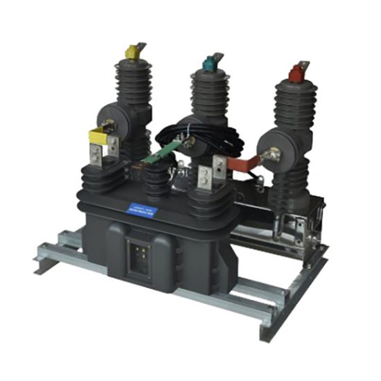
The ZWJ-12 is a single-phase, indoor/outdoor-rated cast-resin voltage transformer (VT) engineered for reliable operation in 10kV distribution networks—equivalent to the IEC-standardized 11kV nominal system voltage. Designed in strict accordance with IEC 61869-3 and GB/T 20840.3, this instrument transformer provides precise voltage scaling from high-voltage primary circuits to standardized secondary outputs (typically 100 V or 100/√3 V), enabling accurate metering, protective relaying, and power quality monitoring.
Operating Principle of Cast-Resin Insulation
The ZWJ-12 employs vacuum pressure impregnation (VPI) epoxy resin technology to encapsulate its magnetic core and windings. This process eliminates air voids and moisture ingress by fully saturating the winding assembly under vacuum before curing under pressure. The resulting monolithic structure exhibits superior dielectric strength (≥30 kV/mm), excellent tracking resistance (CTI ≥600), and minimal partial discharge (<5 pC at 1.2 × Um/√3). Unlike oil-filled alternatives, the solid insulation system requires no fluid containment, eliminating fire hazards and environmental contamination risks. Thermal stability is maintained up to 130°C (Class B insulation), with thermal conductivity of ~0.8 W/m·K ensuring efficient heat dissipation during continuous or transient overloads.
Advantages Over Oil-Immersed Designs
Cast-resin construction offers significant operational and safety benefits compared to traditional oil-immersed VTs. First, it is inherently maintenance-free—no oil sampling, degassing, or leakage monitoring is required. Second, the compact mechanical footprint reduces space requirements in switchgear cubicles by up to 30%. Third, the absence of flammable oil enhances fire safety in confined substations, aligning with IEC 62271-200 arc-containment guidelines. Additionally, the epoxy matrix provides exceptional mechanical rigidity, resisting deformation under short-circuit electromagnetic forces (tested to 20 kA/1s). Environmental resilience is further demonstrated through successful operation in humidity levels up to 95% RH and altitudes ≤1000 m without derating.
Typical Applications Overview
The ZWJ-12 is deployed across utility, industrial, and renewable energy sectors where precision, reliability, and long service life are critical. In urban ring-main units (RMUs), it supplies secondary voltage to digital multifunction meters and directional overvoltage relays. In industrial plants, it interfaces with SCADA systems for real-time voltage monitoring and harmonic analysis. Its robust design also supports integration into solar PV substations, where it enables anti-islanding protection and revenue-grade metering. With a standard accuracy class of 0.2 for metering and 3P for protection, the ZWJ-12 meets stringent grid-code requirements for both billing and fault detection applications.
Technical Specifications
The ZWJ-12 is engineered to deliver consistent performance under defined electrical and environmental parameters. Key specifications are derived from IEC 61869-3 test protocols and validated through type, routine, and special tests during manufacturing.
Rated Electrical Parameters
| Parameter | Value |
|---|---|
| Primary Voltage (Um) | 12 kV (max), 11 kV (IEC nominal), 10 kV (domestic system) |
| Secondary Voltage | 100 V or 100/√3 V (standard); optional 110 V variants available |
| Voltage Ratio | 11000/100 V, 11000/100/√3 V, 10000/100 V, etc. |
| Accuracy Class | Metering: 0.2, 0.5; Protection: 3P, 6P |
| Rated Output (per burden) | 10–100 VA (e.g., 30 VA at 0.2 class, 50 VA at 3P class) |
| Insulation Level (LI/AC) | 75 kV lightning impulse / 28 kV power frequency (1 min) |
| Short-Time Thermal Current | 100 × In for 1 s (protection winding) |
| Frequency | 50 Hz (±0.5 Hz) |
Tolerance on ratio error at rated burden and 80–120% of rated voltage is ±0.2% for 0.2 class and ±3% for 3P class. Phase displacement must not exceed ±10 minutes for metering and ±60 minutes for protection classes under same conditions.
Standard Service Conditions
The ZWJ-12 is rated for operation under normal service conditions as defined in IEC 61869-1:
- Ambient temperature: –25°C to +40°C (storage: –40°C to +70°C)
- Relative humidity: ≤95% non-condensing
- Altitude: ≤1000 m above sea level (derating factor 1.1% per 100 m above 1000 m)
- Pollution degree: III (creepage distance ≥20 mm/kV)
- Installation: Vertical mounting on support bracket; primary terminal torque: 25 N·m
For coastal or chemical-industrial environments, an optional hydrophobic silicone coating can be applied to enhance pollution performance. The transformer’s IP rating is IP00 (bare unit), but when housed in standard RMU or switchgear, overall enclosure IP2X compliance is achieved.
Core and Winding Construction
The magnetic circuit utilizes grain-oriented electrical steel (GOES) laminations (M4 grade, 0.27 mm thickness) with stepped-lap joints to minimize core loss (<0.8 W/kg at 1.7 T, 50 Hz). Primary windings consist of enameled copper wire (Class 180°C insulation), while secondary windings use double-insulated magnet wire with additional polyester tape wrapping. All windings are pre-baked at 120°C for 4 hours before resin casting to ensure moisture removal. The epoxy formulation includes alumina trihydrate (ATH) filler for flame retardancy (UL94 V-0 equivalent) and UV stabilizers for outdoor durability.
Typical Applications
The ZWJ-12’s versatility stems from its dual compliance with international and domestic standards, enabling deployment across diverse grid architectures.
Substation Secondary Metering
In 10kV/11kV primary substations, the ZWJ-12 feeds secondary voltage to Class 0.2S revenue meters for accurate energy billing. Its low phase error ensures compliance with EN 50470-1 and DL/T 614 requirements. For example, in a Chinese municipal utility substation, three ZWJ-12 units (connected in V-V configuration) supply 100/√3 V to a three-phase smart meter, achieving ±0.15% measurement uncertainty over a 24-hour load cycle. The cast-resin body resists condensation in unheated kiosks, preventing insulation degradation that could skew readings.
Industrial Power Distribution
Large manufacturing facilities use the ZWJ-12 for motor protection and power factor correction control. A typical application involves connecting the VT to a microprocessor-based relay (e.g., SEL-351) that monitors undervoltage (27), overvoltage (59), and loss-of-potential (60) conditions. In a steel mill with frequent arc-furnace switching, the ZWJ-12’s high saturation margin (>2.0 × rated voltage) prevents core distortion during voltage sags, maintaining relay coordination integrity. Its 50 VA output capacity supports multiple burdens without exceeding accuracy limits.
Renewable Energy Integration
Solar and wind farms integrate the ZWJ-12 into collector substation switchgear to enable grid-synchronization and fault ride-through (FRT) functions. During islanding events, the VT provides voltage magnitude and phase angle data to anti-islanding relays (e.g., IEEE 1547-compliant). In a 20 MW PV plant in Inner Mongolia, ZWJ-12 units withstand daily thermal cycling (–20°C to +45°C) without cracking due to matched CTE (coefficient of thermal expansion) between resin and copper. The 3P accuracy class ensures reliable operation of over/under-voltage trip schemes during cloud-induced irradiance fluctuations.
Rural and Suburban Distribution Networks
In remote areas with limited maintenance access, the ZWJ-12’s maintenance-free design reduces lifecycle costs. Mounted on pole-top transformers or pad-mounted switchgear, it supplies voltage signals to remote terminal units (RTUs) for distribution automation. A case study in Sichuan province shows 15-year field operation with zero failures, attributed to the resin’s resistance to rodent damage and fungal growth. The compact size allows retrofitting into legacy 10kV cabinets originally designed for oil-type VTs.
Harmonic Monitoring Systems
With increasing nonlinear loads, utilities deploy the ZWJ-12 in power quality analyzers to measure THD (Total Harmonic Distortion). Its flat frequency response (±1% from 45–55 Hz) and low capacitive coupling enable accurate capture of 3rd to 13th harmonics. When paired with a Class A analyzer per IEC 61000-4-30, it supports compliance verification for GB/T 14549 harmonic limits in commercial districts.
Compliance with International Standards
The ZWJ-12’s design and testing rigorously adhere to global and national regulatory frameworks, ensuring interoperability and safety.
IEC 61869-3 Certification Requirements
IEC 61869-3 governs the accuracy, insulation, and thermal performance of inductive voltage transformers. The ZWJ-12 undergoes mandatory type tests including:
- Temperature rise test: ≤60 K for windings at 1.2 × rated output
- Short-circuit withstand: 100 × In for 1 s without damage
- Partial discharge: ≤5 pC at 1.2 × Um/√3
- Accuracy verification: ratio and phase error within class limits at 25%, 50%, 100%, and 120% of rated voltage
Certification is issued by accredited labs (e.g., KEMA, CESI) after successful completion of all tests. The transformer’s nameplate includes the IEC 61869-3 logo and test report number for traceability.
Alignment with GB/T 20840.3
GB/T 20840.3 is China’s national adoption of IEC 61869-3, with minor deviations in test voltages and creepage distances. Key differences include:
- Power frequency withstand: 30 kV (1 min) vs. IEC’s 28 kV for 12 kV Um
- Minimum creepage: 25 mm/kV (vs. IEC’s 20 mm/kV) for pollution degree III
- Burden designation: “VA” instead of “volt-ampere” in labeling
The ZWJ-12 is dual-certified, bearing both CQC (China Quality Certification) and IEC marks. This facilitates procurement by State Grid and Southern Grid, which mandate GB/T compliance for all grid-connected equipment.
Testing and Certification Documentation
Each ZWJ-12 unit ships with a test certificate listing individual results for:
- Insulation resistance (>10 GΩ at 2500 V DC)
- Turns ratio error (e.g., –0.12% at 100 V secondary)
- Polarity (reducing polarity confirmed)
- Dielectric tests passed
Type test reports (valid for 8 years) and routine test records are archived per ISO 9001.
On-Site Testing Procedures
Field commissioning and periodic verification require standardized tests to validate performance and safety.
Insulation Resistance Test
Using a 2500 V megohmmeter, measure insulation resistance between:
- Primary winding and ground
- Secondary windings and ground
- Primary and secondary windings
Acceptance criterion: ≥10 GΩ at 20°C. Correct for temperature using R20 = Rt × 1.5(t–20)/10. Values below 1 GΩ indicate moisture ingress or resin cracking and warrant replacement. Perform before and after dielectric tests to detect insulation damage.
Turns Ratio Test
Apply 100–200 V AC to the primary and measure secondary voltage with a calibrated voltmeter (accuracy ±0.1%). Calculate ratio error: [(Vp/Vs)measured – (Vp/Vs)nominal] / (Vp/Vs)nominal × 100%. Tolerance: ±0.2% for 0.2 class, ±3% for 3P class. Use a dedicated turns ratio tester (e.g., Omicron TTR300) for automated comparison against factory data.
Polarity Verification
Confirm reducing polarity (IEC standard) by applying a low-voltage DC pulse to the primary. Connect a center-zero galvanometer between secondary terminals. A momentary positive deflection upon closing the primary circuit indicates correct polarity. Incorrect polarity causes 180° phase shift, leading to meter reversal or relay misoperation. Document polarity mark alignment (dot convention) on as-built drawings.
Power Frequency Withstand Voltage Test
Apply 28 kV RMS (for 11kV system) at 50 Hz between primary and ground for 1 minute. Secondary windings are short-circuited and grounded. Monitor for flashover, excessive leakage current (>1 mA), or audible discharge. This test validates insulation integrity after transport or prolonged storage. Do not perform if partial discharge exceeds 10 pC during pre-test screening.
Open-Circuit Characteristic Test
Gradually increase primary voltage from 0 to 190 V (≈1.9 × rated secondary) while measuring excitation current. Plot Vs vs. Iexc. Knee point should occur above 150 V. Excessive excitation current (>5 mA at 100 V) indicates core saturation or turn-to-turn shorts. This test is critical after fault exposure to verify magnetic circuit health.
Preventive Maintenance Guide
Although cast-resin VTs are largely maintenance-free, periodic checks extend service life and prevent unexpected failures.
Annual Visual and Functional Inspection
Inspect for:
- Surface cracks, tracking, or discoloration on resin housing
- Loose or corroded terminal connections (torque check: 25 N·m)
- Moisture accumulation in terminal box (if equipped)
- Abnormal heating via infrared thermography (ΔT >10 K above ambient warrants investigation)
Verify secondary voltage under load matches expected values (±2%). Clean housing with non-abrasive cloth and isopropyl alcohol; avoid high-pressure water jets.
Five-Year Dielectric and Accuracy Revalidation
Every 60 months, repeat:
- Insulation resistance test
- Turns ratio and polarity tests
- Partial discharge measurement (if PD detector available)
Compare results to baseline commissioning data. Drift in ratio error >0.1% or insulation resistance drop >50% indicates aging.
Maintenance Intervals and Fault Diagnosis
| Interval | Action | Fault Indicator |
|---|---|---|
| Annually | Visual inspection, IR scan | Cracks, overheating |
| 5 Years | Electrical retesting | Ratio drift, low IR |
| After Fault | Full suite of tests | Relay misoperation |
| End-of-Life (25+ yrs) | Replace regardless of condition | Embrittlement |
Common failure modes include terminal corrosion (due to galvanic mismatch) and resin embrittlement from UV exposure (outdoor units). Never attempt field repair—replace the entire unit.
Conclusion
The ZWJ-12 11kV cast-resin voltage transformer represents a benchmark in medium-voltage instrumentation, combining IEC 61869-3 and GB/T 20840.3 compliance with robust engineering for demanding utility and industrial environments. Its epoxy-encapsulated GOES core ensures decades of stable ratio accuracy, while the absence of liquid insulation eliminates fire risk and maintenance overhead. Field-proven in climates ranging from tropical humidity to arid cold, the ZWJ-12 delivers reliable secondary voltage for critical metering and protection functions across 10kV/11kV networks. With a design life of 25–30 years under standard service conditions, it offers a compelling total cost of ownership compared to oil-immersed alternatives. Adherence to rigorous type-testing protocols guarantees performance consistency, making it a preferred choice for modern smart grids requiring high data fidelity and operational resilience. Proper commissioning and adherence to the outlined preventive maintenance schedule further maximize asset longevity and system reliability.
Frequently Asked Questions (FAQ)
Q1: Can the ZWJ-12 be used in a 10kV system even though it’s rated 11kV?
Yes. The 11kV rating refers to the IEC-standardized highest voltage for equipment (Um = 12 kV). It is fully compatible with 10kV nominal systems (phase-to-phase), which operate within the 11kV equipment’s design envelope.
Q2: What is the maximum allowable burden for a 0.2-class ZWJ-12?
The rated output defines the maximum burden. For example, a ZWJ-12 labeled “30 VA, 0.2” must not exceed 30 VA total connected burden (including wiring impedance) to maintain ±0.2% ratio error.
Q3: Is partial discharge testing required during routine maintenance?
Not routinely—it’s a type test. However, if insulation resistance drops below 1 GΩ or after a major fault, PD measurement (<10 pC acceptable) helps assess internal insulation health.
Q4: How do I verify reducing polarity in the field?
Use the DC kick method: apply a 12 V battery momentarily to the primary. A positive galvanometer kick on the secondary confirms reducing polarity (dot-to-dot alignment).
Q5: Can the ZWJ-12 be installed outdoors without a shelter?
Yes—the cast-resin housing is UV-stabilized and rated for direct outdoor exposure. However, in heavy pollution zones (e.g., coastal), periodic cleaning of the surface is recommended to prevent flashover.
Q6: What causes ratio error drift over time?
Primary causes include core aging (from thermal cycling), turn-to-turn shorts (from insulation degradation), or loose connections increasing burden. Annual ratio checks detect these early.