Contenido del artículo
IEC 61869-2 Certified 11kV Current Transformer LFS-10 for Metering & Protection Applications
Introduction to the LFS-10 Current Transformer
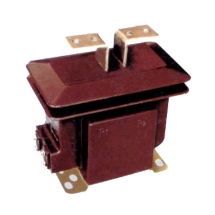
The LFS-10 is a dry-type, cast-resin insulated current transformer (CT) engineered for reliable operation in 11kV (IEC standard) or 10kV (domestic system equivalent) medium-voltage networks. Designed in strict compliance with IEC 61869-2 and GB/T 20840.2, this instrument transformer serves dual roles in electrical energy metering and protective relaying within substations, industrial facilities, and renewable energy installations. Its robust construction leverages modern epoxy resin casting technology combined with grain-oriented electrical steel (GOES) cores to ensure high accuracy, long-term stability, and immunity to environmental stressors.
Unlike traditional oil-immersed CTs, the LFS-10 eliminates fire hazards, oil leakage risks, and complex maintenance requirements. The solid dielectric barrier formed by vacuum pressure impregnated (VPI) epoxy resin provides superior partial discharge resistance (<5 pC at 1.2 × Um/√3), excellent tracking resistance (CTI > 600 V), and mechanical rigidity suitable for both indoor and outdoor environments. This makes the LFS-10 particularly well-suited for urban substations, compact switchgear, and locations where environmental safety and space constraints are critical design factors.
Operating Principle of Cast-Resin Insulation
Cast-resin insulation in the LFS-10 functions as both a structural support and a high-dielectric-strength barrier between primary and secondary windings. The manufacturing process involves vacuum degassing of epoxy resin mixed with silica fillers, followed by pressure injection into precision molds containing pre-wound copper secondary coils and a laminated GOES core. This VPI technique ensures complete void elimination, resulting in a homogeneous, non-hygroscopic solid that withstands thermal cycling from –40°C to +40°C without cracking or delamination. The resin’s relative permittivity (εr ≈ 4.5) and volume resistivity (>1014 Ω·cm) provide consistent electric field distribution, minimizing localized stress concentrations that could lead to premature aging or breakdown under continuous 11kV service voltage.
Advantages Over Oil-Immersed Designs
Compared to oil-filled counterparts, the LFS-10 offers significant operational and safety benefits. It requires no oil sampling, gas monitoring, or conservator tanks, reducing lifecycle costs by up to 30%. The absence of flammable liquids allows installation in confined spaces such as underground vaults or commercial buildings without fire-rated enclosures. Additionally, cast-resin CTs exhibit faster thermal response due to higher thermal conductivity (~0.8 W/m·K vs. ~0.12 W/m·K for mineral oil), enabling better overload tolerance during transient fault conditions. Field data from European grid operators indicate a mean time between failures (MTBF) exceeding 200,000 hours for cast-resin CTs like the LFS-10, compared to ~150,000 hours for oil types under similar loading profiles.
Typical Application Overview
The LFS-10 is commonly deployed in 11kV ring main units (RMUs), metal-clad switchgear, and pad-mounted transformers across utility distribution networks. Its dual-core configuration—typically one core rated for 0.5 class (metering) and another for 5P10 or 5P20 (protection)—enables simultaneous connection to revenue meters and overcurrent relays without cross-interference. In solar PV substations, it interfaces with SCADA systems for real-time current monitoring, while in mining operations, its vibration-resistant construction ensures reliability under mechanical shock. With an IP54 ingress protection rating when mounted vertically, the LFS-10 performs reliably in dusty or humid coastal environments without derating.
Technical Specifications
The LFS-10 current transformer is engineered to meet stringent performance criteria under defined service conditions. Key parameters are derived from IEC 61869-2 Clause 5 and validated through type, routine, and special tests per manufacturer protocols.
| Parameter | Value |
|---|---|
| Rated Voltage (Um) | 12 kV (system voltage 11 kV) |
| Domestic System Voltage | 10 kV |
| Primary Current (Ip) | 50 A to 3150 A (standard ratios) |
| Secondary Current (Is) | 1 A or 5 A |
| Accuracy Class (Metering) | 0.2, 0.5, or 1.0 per IEC 61869-2 |
| Accuracy Class (Protection) | 5P10, 5P15, 5P20 |
| Rated Output (Sn) | 5 VA, 10 VA, 15 VA, 30 VA (per core) |
| Short-Time Thermal Current (Ith) | 20 kA for 1 s (at 50 Hz) |
| Dynamic Withstand Current | 50 kA peak |
| Insulation Level (LI/AC) | 75 kV / 28 kV (1 min power frequency) |
| Partial Discharge | <5 pC at 1.2 × Um/√3 |
| Ambient Temperature Range | –40°C to +40°C |
| Altitude Limit | ≤1000 m above sea level (derating required above) |
| Relative Humidity | Up to 95% non-condensing |
Standard Service Conditions
The LFS-10 is rated for normal service conditions as defined in IEC 61869-1: ambient temperature between –40°C and +40°C, daily average not exceeding +35°C, relative humidity up to 95% at 25°C, and installation altitude not exceeding 1000 m. At altitudes above 1000 m, the external insulation must be derated by 1% per 100 m increment for power frequency withstand voltage. For example, at 2000 m, the AC test voltage reduces from 28 kV to 25.2 kV. The transformer must be installed vertically with primary conductor aligned axially to avoid mechanical stress on resin bushings. Deviations from these conditions require engineering review to prevent accelerated aging or reduced short-circuit withstand capability.
Core and Winding Configuration
Each LFS-10 unit contains one or two independent magnetic circuits wound on grain-oriented electrical steel (GOES) cores with thicknesses of 0.23–0.30 mm. The GOES material exhibits core loss ≤1.0 W/kg at 1.7 T and 50 Hz, ensuring minimal heating under continuous load. Secondary windings use electrolytic-tough-pitch (ETP) copper with enamel insulation rated for 180°C (Class H). Terminals are labeled per IEC 61869-2: P1/P2 for primary polarity, and S1/S2 for secondary, with S1 designated as the “reducing polarity” terminal. Burden impedance must not exceed the rated output divided by Is2; e.g., for a 10 VA, 5 A CT, maximum burden = 10 / 25 = 0.4 Ω.
Typical Applications
The LFS-10 current transformer is deployed across diverse power infrastructure segments due to its dual functionality, compact form factor, and environmental resilience.
Substation Secondary Metering
In 11kV/0.4kV distribution substations, the LFS-10 provides accurate current signals to kWh meters, demand recorders, and power quality analyzers. Its 0.5-class metering core ensures billing accuracy within ±0.5% error at 5–120% of rated current, satisfying regulatory requirements in most jurisdictions. Installed on outgoing feeders, it enables precise load profiling and loss allocation. When paired with digital meters featuring IEC 61850-9-2 LE compatibility, the LFS-10 supports sampled value transmission without analog-to-digital conversion errors. Critical for utility revenue protection, its phase displacement remains below ±15 minutes at 100% In, minimizing reactive energy measurement drift.
Industrial Power Distribution
Within manufacturing plants, the LFS-10 monitors motor feeder currents for both energy management and motor protection. Its 5P20 protection core delivers linear output up to 20× rated current, allowing overcurrent relays (e.g., IEC 60255-compliant) to distinguish between startup inrush and fault currents. In arc flash mitigation schemes, fast-acting relays use LFS-10 signals to trip within 30 ms during bolted faults. The cast-resin body resists chemical vapors common in petrochemical facilities, and its non-tracking surface prevents flashovers in high-conductivity dust environments. Typical installations include switchgear line-ups feeding 1 MW+ induction motors or variable frequency drives.
Renewable Energy Integration
Solar and wind farms utilize the LFS-10 at the point of interconnection (POI) to grid-tie transformers. Here, it supplies current data to synchrophasors (PMUs) and anti-islanding relays. The low remanence of GOES cores ensures rapid demagnetization after grid faults, preventing false tripping during voltage recovery. In microgrids operating in islanded mode, the LFS-10’s stable ratio under harmonic distortion (tested up to 15% THD) maintains relay coordination. Its lightweight design (≈18 kg) simplifies mounting on pole-top transformers in remote solar farms, where access for maintenance is limited.
Rural and Suburban Distribution Networks
For rural electrification projects, the LFS-10’s maintenance-free operation reduces operational expenditure in areas with limited technical staff. Mounted on single-pole structures or pad-mounted transformers, it feeds data to remote terminal units (RTUs) for SCADA-based load balancing. Its ability to operate at 100% rated current continuously without thermal derating supports seasonal load surges (e.g., agricultural irrigation pumps). In suburban ring main units, dual-core variants allow one core for AMI metering and the other for sectionalizer control, optimizing asset utilization without compromising protection integrity.
Compliance with International Standards
The LFS-10 is certified to IEC 61869-2:2012 (“Instrument transformers – Part 2: Additional requirements for current transformers”) and aligns with China’s GB/T 20840.2-2014, which adopts IEC content with minor national deviations.
IEC 61869-2 Compliance Details
IEC 61869-2 defines performance classes, test methods, and marking requirements for CTs. The LFS-10 meets all mandatory clauses: accuracy verification at 5%, 20%, 100%, and 120% of rated current; temperature rise limits (<60 K for windings); and short-circuit withstand per Annex C. Its composite error for 5P20 class is ≤10% at 20× In with rated burden. Markings include rated voltage, ratio, accuracy class, output, and polarity symbols per Clause 8. Type tests—conducted once per design—include temperature rise, short-circuit, and impulse voltage tests. Routine tests (per unit) cover ratio, polarity, insulation resistance (>1000 MΩ at 2500 V DC), and power frequency withstand.
GB/T 20840.2 Alignment and Differences
GB/T 20840.2 mirrors IEC 61869-2 but specifies additional requirements for Chinese grids: mandatory seismic testing (0.3g horizontal acceleration), and stricter partial discharge limits (<3 pC at Um/√3). While IEC permits 1 A or 5 A secondaries, GB standards often mandate 5 A for legacy compatibility. The LFS-10’s domestic variant includes reinforced core clamping to meet seismic demands and uses thicker resin walls (≥25 mm creepage distance) to satisfy pollution degree 3 requirements in industrial zones. Despite these differences, the core electromagnetic design remains identical, ensuring global interoperability.
Testing and Certification Requirements
Certification requires third-party validation by accredited labs (e.g., KEMA, CESI, or China Electric Power Research Institute). Type test reports must demonstrate compliance with all IEC 61869-2 Annexes. For export to EU markets, CE marking under EMC Directive 2014/30/EU is required, verified via conducted emission tests (EN 61000-6-4). In North America, although IEEE C57.13 applies, the LFS-10 can be used in IEC-based projects with engineering justification. All units undergo factory acceptance tests (FAT) including visual inspection, dimension check, and secondary winding resistance measurement (tolerance ±5% of design value).
On-Site Testing Procedures
Post-installation verification ensures the LFS-10 operates within design parameters before energization.
Insulation Resistance Test
Using a 2500 V DC megohmmeter, measure insulation resistance between primary-to-secondary, primary-to-ground, and secondary-to-ground. Acceptance criterion: ≥1000 MΩ at 25°C. Correct for temperature using RT = R25 × 2(25–T)/10. Low readings (<100 MΩ) indicate moisture ingress or resin cracking. Re-test after 24-hour drying if humidity exceeds 80%.
Turns Ratio Test
Apply 1–5 V AC to secondary winding and measure induced primary voltage (open-circuit method). Calculate ratio = Vp/Vs. Compare to nameplate; tolerance per IEC 61869-2 is ±0.25% for metering classes, ±1% for protection. Alternatively, use a dedicated CT analyzer injecting 10–50% In into primary and measuring secondary current.
Polarity Test
Connect a 1.5 V DC battery between P1 (+) and P2 (–). Momentarily close the circuit while monitoring a center-zero galvanometer across S1 (+) and S2 (–). A positive kick confirms reducing polarity. Incorrect polarity causes watt-hour meters to register reverse energy and protection relays to misoperate during faults.
Power Frequency Withstand Voltage Test
Apply 28 kV RMS at 50 Hz for 1 minute between primary and grounded secondary/core. Use a calibrated HV test set with automatic trip at 10 mA leakage current. Partial discharge should remain <10 pC during test. Do not perform if ambient humidity >80% or surface is contaminated.
Short-Circuit Test (for CT)
Not applicable as a field test—short-circuit withstand is verified only during type testing. However, verify secondary circuits are never left open during operation. Always short S1–S2 before disconnecting meters to prevent dangerous overvoltages (>5 kV) due to core saturation.
Preventive Maintenance Guide
Although cast-resin CTs are largely maintenance-free, periodic checks extend service life beyond 25 years.
Periodic Inspection Protocol
Conduct annual visual inspections: check for resin cracks, terminal corrosion, or tracking marks. Clean surfaces with isopropyl alcohol if dust accumulation exceeds 0.5 mm thickness. Verify torque on M8 secondary terminals (8–10 N·m) and ensure grounding strap resistance <0.1 Ω. Use infrared thermography during peak load to detect abnormal heating (>10 K above ambient indicates winding defect).
Maintenance Intervals and Fault Diagnosis
| Interval | Action |
|---|---|
| Annually | Visual inspection, IR scan, terminal torque check |
| Every 5 Years | Insulation resistance test, ratio verification |
| After Major Fault | Full suite: ratio, polarity, PD measurement |
Common faults include open secondary circuits (causing insulation puncture), core saturation from DC offset (evidenced by distorted waveform), and moisture-induced surface leakage. If ratio error exceeds 2× initial value, replace the unit—core degradation is irreversible.
Conclusion
The LFS-10 11kV cast-resin current transformer represents a mature, field-proven solution for metering and protection in modern medium-voltage networks. Its compliance with IEC 61869-2 and GB/T 20840.2 ensures global acceptance, while the VPI epoxy resin construction delivers unmatched safety, environmental resilience, and longevity. With a design life of 25–30 years under standard service conditions, the LFS-10 minimizes total cost of ownership through zero fluid maintenance, high short-circuit withstand (20 kA/1s), and dual-core flexibility. Its GOES core guarantees stable accuracy across load ranges, critical for both revenue metering and selective protection coordination. As utilities transition toward compact, fire-safe switchgear and digital substations, the LFS-10 remains a cornerstone component—engineered not for obsolescence, but for decades of dependable service in the world’s most demanding electrical environments.