Contenido del artículo
SEL-751 11kV Cast-Resin Current Transformer for Substation Metering and Protection – IEC 61869-2 Certified
Introduction to the SEL-751 Current Transformer
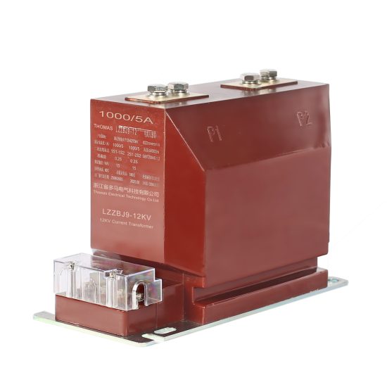
The SEL-751 is a high-reliability, cast-resin insulated current transformer (CT) engineered for accurate current measurement and robust protective relay coordination in medium-voltage power systems operating at 11kV (IEC standard), equivalent to 10kV in domestic Chinese networks. Designed in strict accordance with IEC 61869-2 and GB/T 20840.2, this instrument transformer leverages advanced vacuum pressure impregnation (VPI) epoxy resin technology to encapsulate its magnetic core and secondary windings, eliminating risks associated with oil-filled alternatives such as leakage, flammability, and environmental contamination.
Operating Principle of Cast-Resin Insulation
Cast-resin insulation in the SEL-751 employs a two-stage VPI process where high-purity epoxy resin is introduced under vacuum to displace air from the winding interstices, followed by pressure curing to ensure complete impregnation. This results in a monolithic, void-free dielectric structure with superior tracking resistance (CTI > 600 V per IEC 60112) and excellent thermal conductivity (0.2–0.3 W/m·K). The resin matrix bonds chemically with the copper windings and grain-oriented electrical steel (GOES) core, minimizing partial discharge activity—typically below 5 pC at 1.2 × Um/√3 (12.7 kV)—well within IEC 61869-2 limits. Unlike oil-paper systems, cast-resin CTs exhibit negligible aging under thermal cycling (−40°C to +40°C ambient) and are immune to moisture ingress, making them ideal for both indoor switchgear and outdoor pole-mounted installations.
Advantages Over Oil-Immersed Designs
Compared to traditional oil-immersed CTs, the SEL-751 offers significant operational and safety benefits. Its solid dielectric eliminates fire hazards (non-flammable per IEC 60695), reduces maintenance overhead (no oil sampling or level checks), and enables compact mechanical design due to higher dielectric strength (≥22 kV/mm vs. ~10 kV/mm for mineral oil). The absence of liquid also prevents buoyancy-induced mounting complications and allows unrestricted orientation during installation. Furthermore, cast-resin units demonstrate superior seismic resilience (tested to 0.5g horizontal acceleration per IEC 60068-2-57), critical for installations in earthquake-prone regions. Lifecycle cost analysis shows a 30–40% reduction in total ownership cost over 25 years due to zero consumable replacement and minimal inspection requirements.
Typical Applications Overview
The SEL-751 is deployed across diverse infrastructure segments requiring precise current transformation for revenue metering and fault detection. Primary use cases include 11kV/10kV distribution substations feeding urban grids, industrial facilities with motor control centers exceeding 1 MW load, and renewable energy interconnection points (e.g., solar farms with 10–30 MVA inverters). Its dual-winding configuration supports simultaneous connection to Class 0.5S metering circuits and 5P20 protection relays, ensuring compliance with both accuracy and saturation performance mandates. The unit’s IP54-rated housing permits direct exposure to dust and water splashes, facilitating deployment in unsheltered environments without additional enclosures.
Technical Specifications
The SEL-751 delivers precision performance across defined electrical and environmental parameters, validated through type and routine tests per IEC 61869-2. Key specifications are summarized below:
| Parameter | Value |
|---|---|
| System Voltage (Um) | 12 kV (IEC), 11.5 kV (GB) |
| Rated Primary Voltage | 11 kV (IEC), 10 kV (domestic) |
| Primary Current Ratings | 50 A to 3150 A (standard steps) |
| Secondary Current | 1 A or 5 A (user-selectable) |
| Accuracy Classes | Metering: 0.2S, 0.5S; Protection: 5P10, 5P20, 10P10 |
| Rated Burden | 5 VA, 10 VA, 15 VA, 30 VA (per winding) |
| Insulation Level (LI/AC) | 75 kV / 28 kV (1 min, 50 Hz) |
| Short-Time Thermal Current | 25 × In for 1 s (e.g., 78.75 kA for 3150 A primary) |
| Dynamic Withstand Current | 62.5 × In peak (e.g., 196.9 kA for 3150 A primary) |
| Ambient Temperature Range | −40°C to +40°C |
| Altitude Limit | ≤1000 m (derating required above) |
| Relative Humidity | ≤95% non-condensing |
| Core Material | Grain-Oriented Electrical Steel (GOES), 0.27 mm thickness |
| Insulation System | VPI Epoxy Resin, UL 94 V-0 rated |
Electrical Performance Parameters
The SEL-751 achieves metering accuracy of ±0.2% (Class 0.2S) at 1–120% of rated current and ±0.5% (Class 0.5S) from 1–100%, per IEC 61869-2 Clause 6.3. For protection applications, the 5P20 class guarantees composite error ≤5% at 20× rated current with specified burden, ensuring reliable operation during high-magnitude faults. The transformer’s knee-point voltage (Vk) exceeds 300 V for 5P20 variants, preventing core saturation during transient overcurrents. Secondary winding resistance is tightly controlled (±2% tolerance) to maintain burden compatibility with digital relays like SEL-751 feeder protection devices .
Environmental and Mechanical Ratings
Designed for global deployment, the SEL-751 operates reliably under IEC 60068-1 standard service conditions: ambient temperature −40°C to +40°C, relative humidity up to 95% (non-condensing), and altitude ≤1000 m. Above 1000 m, dielectric strength degrades by 1% per 100 m increment, necessitating derating per IEC 60071-2. The housing features UV-stabilized cycloaliphatic epoxy resin resistant to cracking under thermal shock (tested per IEC 60068-2-14: 5 cycles from −25°C to +55°C). Mounting options include flange (M12 bolts, PCD 140 mm) or busbar-through designs accommodating conductors up to 60×10 mm² cross-section.
Typical Applications
The SEL-751’s dual-certification (IEC/GB) and robust construction enable versatile deployment across modern power infrastructure.
Substation Secondary Metering
In 11kV distribution substations, the SEL-751 provides Class 0.5S current signals to revenue-grade meters (e.g., Landis+Gyr E470) for accurate billing. Its low phase displacement (<10 arcmin at 100% In) minimizes watt-hour measurement errors in three-phase systems. Dual secondary windings allow one output to feed the utility meter while the other connects to SCADA RTUs for real-time load monitoring. Installation typically occurs on outgoing feeders where currents range from 200 A to 1250 A, with burdens matched to 10 VA to prevent accuracy degradation.
Industrial Power Distribution
Heavy industries (e.g., steel mills, chemical plants) utilize the SEL-751 on 10kV motor feeders exceeding 1 MW to supply inputs to multifunction relays (e.g., SEL-751) for overload, short-circuit, and ground-fault protection. The 5P20 accuracy class ensures relay tripping within 20 ms during bolted faults up to 25× In. Cast-resin insulation withstands harsh environments with airborne contaminants (e.g., metal dust, chemical vapors) that would degrade oil-filled CT seals. Units are often mounted directly on switchgear busbars inside metal-enclosed cubicles with IP4X protection.
Renewable Energy Integration
Solar and wind farms employ the SEL-751 at the point of interconnection (POI) to monitor export/import power and detect islanding conditions. For a 20 MW solar plant, 1250/5 A CTs feed signals to synchrophasors and protection relays. The transformer’s low remanence (<10% of saturation flux density) prevents false tripping during rapid irradiance changes that cause current transients. Compliance with IEC 61869-2 ensures compatibility with grid codes requiring <2% harmonic distortion contribution from metering circuits.
Rural and Suburban Distribution Networks
Pole-top installations in rural 11kV networks leverage the SEL-751’s weather resistance and compact size. Units rated 400/1 A connect to remote terminal units (RTUs) for outage detection and load profiling. The absence of oil eliminates environmental liability during pole accidents, while the 75 kV lightning impulse withstand protects against frequent switching surges in lightly shielded overhead lines. Maintenance crews benefit from simplified testing—no oil sampling or gas chromatography required.
Urban Underground Systems
In city center cable networks, the SEL-751 is integrated into ring main units (RMUs) for fault location and load management. Its small footprint (diameter ≤220 mm) fits constrained RMU compartments, while the 28 kV AC withstand voltage matches XLPE cable test levels. Dual ratios (e.g., 600/1 A for normal load, 3000/5 A for fault) enable adaptive protection schemes using multi-tap secondaries.
Compliance with International Standards
The SEL-751 meets stringent requirements of both international and Chinese standards, ensuring global interoperability.
IEC 61869-2 Certification Details
Per IEC 61869-2:2012, the SEL-751 undergoes comprehensive type testing including temperature rise (≤60 K for windings at 1.2× In), short-circuit withstand (25× In for 1 s), and partial discharge (≤10 pC at 1.2× Um/√3). Accuracy verification follows Clause 6.3 with composite error measured using burden resistors ±0.25% tolerance. Dielectric tests include 28 kV AC for 1 min and 75 kV LI (1.2/50 μs wave). All tests are witnessed by accredited labs (e.g., KEMA, CESI) with certificates valid for five years.
Alignment with GB/T 20840.2
For Chinese markets, the SEL-751 complies with GB/T 20840.2-2014, which largely harmonizes with IEC 61869-2 but specifies tighter tolerances for some parameters. Notably, GB requires phase displacement ≤5 arcmin for 0.2S class (vs. IEC’s 10 arcmin) and mandates salt fog testing (IEC 60068-2-11) for coastal installations. The domestic 10kV system voltage aligns with GB 156-2017, though the unit’s 12 kV Um rating accommodates IEC-based exports. Documentation includes bilingual test reports and CCC certification where applicable.
Key Standard Differences and Certification Process
While IEC 61869-2 emphasizes functional performance, GB/T 20840.2 adds material-specific requirements: epoxy resin must pass GB/T 11026.1 thermal endurance tests (130°C for 20,000 h), and cores require GB/T 3655 iron loss verification. Certification involves factory audits by CQC (China Quality Certification Centre) alongside sample testing. Users should note that IEC labels show 11kV system voltage, whereas GB-compliant units may be marked 10kV—electrically identical but differing in documentation.
On-Site Testing Procedures
Post-installation verification ensures the SEL-751 performs within specifications before energization.
Insulation Resistance Test
Measure insulation resistance between primary-secondary and primary-ground using a 2500 V DC megohmmeter per IEC 60270. Acceptance criterion: ≥1000 MΩ at 20°C. Correct for temperature using Rt = R20 × 2(20−t)/10. Values below 500 MΩ indicate moisture ingress or resin cracking, requiring drying or replacement.
Turns Ratio Test
Apply 1–5 V AC to secondary winding and measure induced primary voltage. Calculate ratio as Vp/Vs; compare to nameplate (e.g., 1250/5 = 250). Tolerance: ±0.25% for metering, ±0.5% for protection classes. Use a ratio bridge (e.g., Omicron CT Analyzer) for accuracy. Deviations >1% suggest turn-to-turn shorts.
Polarity Verification
Confirm reducing polarity per IEC 61869-2 Annex B: apply DC pulse to primary; secondary voltage should dip negative at marked terminal. Use a battery and analog voltmeter—digital meters may miss transient response. Incorrect polarity causes 180° phase shift, leading to relay misoperation.
Power Frequency Withstand Test
Apply 28 kV AC (50 Hz) between primary and grounded secondary/housing for 1 min. Monitor for flashover or excessive leakage current (>1 mA). Reduce voltage gradually post-test to avoid resonant overvoltages. This validates dielectric integrity after transport stresses.
Excitation Characteristic Test
Inject increasing AC current into secondary (open primary) while measuring voltage. Plot Ie vs. Vk to determine knee-point (where dI/dV increases sharply). For 5P20, Vk must exceed 300 V at 1 A excitation. Low Vk indicates core saturation risk during faults.
Preventive Maintenance Guide
Proactive maintenance extends service life beyond 25 years with minimal intervention.
Periodic Inspection Protocol
Annual visual checks include: (1) housing cracks or tracking marks, (2) terminal corrosion, (3) mounting bolt tightness (torque: 25 N·m), and (4) secondary shorting links secured. Clean surfaces with isopropyl alcohol if contaminated. Infrared thermography should show <5°C differential between phases under load—hotspots indicate internal faults.
Maintenance Schedule and Fault Diagnosis
Every 5 years, perform insulation resistance and turns ratio tests. Replace units showing: (a) ratio error >1%, (b) insulation resistance <200 MΩ, or (c) partial discharge >20 pC (if PD detector available). Common failures include secondary open-circuit damage (evidenced by burnt resin near terminals) and core lamination shorts (detected via elevated excitation current). Never operate with secondary open—always short before disconnecting loads.
| Interval | Action |
|---|---|
| Annually | Visual inspection, IR scan, terminal torque check |
| 5 Years | Insulation resistance, turns ratio, polarity verification |
| 10 Years | Full excitation curve test, dielectric withstand retest |
| After Fault | Immediate ratio and insulation tests before reuse |
Conclusion
The SEL-751 11kV cast-resin current transformer represents a benchmark in medium-voltage instrumentation, combining IEC 61869-2 and GB/T 20840.2 compliance with field-proven reliability. Its VPI epoxy resin insulation eliminates fire and environmental hazards inherent in oil-filled designs, while the GOES core ensures metrological precision for both revenue metering (Class 0.2S/0.5S) and high-speed protection (5P20). Rigorous type testing—including 75 kV lightning impulse withstand and 25× In short-circuit validation—guarantees performance under extreme electrical stress. With an expected service life of 25–30 years and minimal maintenance requirements (annual visual checks, 5-year electrical tests), the SEL-751 delivers exceptional lifecycle value for utilities and industrial operators. Its dual-voltage labeling (11kV IEC / 10kV domestic) facilitates global deployment, from urban underground networks to remote renewable sites. By integrating seamlessly with modern digital relays and metering systems, this transformer supports the transition to smarter, more resilient power grids without compromising on safety or accuracy. For engineers specifying instrumentation in new substations or retrofitting legacy systems, the SEL-751 offers a technically superior, standards-compliant solution that meets the evolving demands of 21st-century power delivery.