Article Content
SEL-751 11kV Cast-Resin Current Transformer for Substation Metering and Protection – IEC 61869-2 Certified
Introduction to the SEL-751 Current Transformer
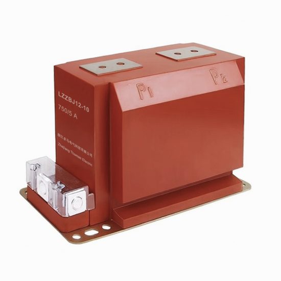
The SEL-751 is a high-reliability, cast-resin insulated current transformer (CT) engineered for dual-purpose applications in electrical power systems—specifically for accurate metering and dependable protection functions at the 11kV distribution level (equivalent to 10kV in domestic Chinese networks). Designed in strict accordance with IEC 61869-2 and GB/T 20840.2, this instrument transformer leverages advanced vacuum pressure impregnation (VPI) epoxy resin technology to deliver superior dielectric strength, environmental resilience, and long-term operational stability.
Operating Principle of Cast-Resin Insulation
Cast-resin insulation in the SEL-751 employs a two-component cycloaliphatic epoxy system cured under controlled vacuum and pressure conditions. This VPI process eliminates air voids and moisture ingress pathways, resulting in a homogeneous, non-hygroscopic solid dielectric matrix that fully encapsulates the primary conductor and secondary windings. The resin’s high tracking resistance (>600 V per IEC 60112) and thermal class F (155°C) rating ensure stable performance under continuous load and transient overcurrent conditions. Unlike oil-filled CTs, the solid resin construction eliminates fire hazards, leakage risks, and maintenance-intensive sealing systems, making it ideal for indoor switchgear and outdoor pole-mounted installations alike.
Advantages Over Oil-Immersed Designs
Compared to traditional oil-immersed current transformers, the SEL-751’s cast-resin design offers significant technical and operational benefits. First, it achieves higher partial discharge inception voltage (>20 kV peak at 50 Hz), reducing insulation degradation over time. Second, its compact footprint—enabled by the high dielectric strength of epoxy resin (≥20 kV/mm)—allows integration into space-constrained medium-voltage switchboards. Third, the absence of liquid insulation eliminates environmental compliance issues related to oil containment and disposal. Finally, the mechanical rigidity of the resin housing provides excellent vibration damping, critical in industrial environments with heavy motor loads or nearby rail infrastructure. These attributes collectively enhance lifecycle reliability while reducing total cost of ownership.
Typical Applications Overview
The SEL-751 is deployed across diverse 11kV/10kV infrastructure segments. In utility substations, it feeds revenue-grade metering systems and digital protective relays such as SEL-751A feeder protection units. Industrial facilities use it for energy monitoring in motor control centers and arc-flash mitigation schemes. Renewable integration points—such as solar farm collector substations—rely on its linear response up to 20× rated current for accurate fault detection during grid disturbances. Its robust design also suits rural distribution networks where temperature extremes (-40°C to +40°C) and humidity fluctuations challenge conventional CTs.
Technical Specifications
The SEL-751 current transformer is engineered to meet stringent performance criteria under both normal and fault conditions. Below is a comprehensive specification table followed by detailed environmental and operational parameters.
| Parameter | Value |
|---|---|
| Rated Voltage (IEC) | 11 kV |
| Rated Voltage (Domestic) | 10 kV |
| Primary Current Ratings | 50 A to 3000 A (standard); custom up to 4000 A |
| Secondary Current | 1 A or 5 A (user-selectable) |
| Accuracy Class (Metering) | 0.2S, 0.5S per IEC 61869-2 |
| Accuracy Class (Protection) | 5P10, 5P20, 10P10 per IEC 61869-2 |
| Rated Burden | 2.5 VA to 30 VA (depending on class) |
| Insulation Level (Um) | 12 kV |
| Power Frequency Withstand Voltage | 28 kV rms, 1 min |
| Lightning Impulse Withstand Voltage | 75 kV peak (1.2/50 μs) |
| Core Material | Grain-Oriented Electrical Steel (GOES), 0.23 mm lamination |
| Short-Time Thermal Current | 25 kA for 1 s (at 50 Hz) |
| Dynamic Withstand Current | 62.5 kA peak |
| Ambient Temperature Range | -40°C to +40°C |
| Altitude Limit | ≤1000 m (derating required above) |
Standard Service Conditions
The SEL-751 is rated for standard service conditions as defined in IEC 61869-2 Clause 5.1. It operates reliably in ambient temperatures from -40°C to +40°C, with relative humidity up to 100% (condensation permissible). Installation altitude must not exceed 1000 meters above sea level; for sites between 1000–2000 m, the power frequency withstand voltage must be reduced by 1% per 100 m increment. The transformer is designed for continuous operation at 1.2× rated primary current without exceeding thermal limits. Pollution degree is classified as PD III (medium conductivity dust, temporary condensation), suitable for most industrial and outdoor environments. Indoor installations require minimum IP2X enclosure protection to prevent accidental contact.
Core and Winding Design
The magnetic circuit utilizes high-permeability GOES (M4 grade) laminations with a maximum specific loss of 0.95 W/kg at 1.7 T and 50 Hz. Core joints are precisely interleaved to minimize flux leakage and excitation current. Secondary windings are wound with electrolytic-tough-pitch (ETP) copper wire, insulated with Class F enamel, and embedded directly into the resin matrix during casting to prevent movement under electromagnetic forces. For dual-ratio configurations, taps are brought out via sealed terminal blocks rated for 600 V. The primary conductor is either a solid copper bar (for ≤1250 A) or a tubular aluminum bus (for >1250 A), both fully encapsulated to eliminate corona discharge at 11kV operating voltage.
Typical Applications
The SEL-751’s dual-accuracy design enables simultaneous support of revenue metering and protective relaying in modern power systems. Its robust construction and precise error characteristics make it suitable for demanding scenarios across multiple sectors.
Substation Secondary Metering
In 11kV/10kV distribution substations, the SEL-751 supplies Class 0.2S or 0.5S secondary current to AMI (Advanced Metering Infrastructure) systems and SCADA RTUs. Its low phase displacement (<±10 minutes at 1–120% rated current) ensures accurate kWh and kVARh measurement even under light-load conditions typical of nighttime residential demand. When paired with digital meters compliant with IEC 62053-22, it meets regulatory requirements for billing accuracy in deregulated markets. The transformer’s thermal stability prevents ratio drift during seasonal load variations, a common issue with lower-grade CTs using non-oriented steel cores.
Industrial Power Distribution
Heavy industrial plants—such as steel mills, cement factories, and data centers—deploy the SEL-751 on main incomers and large motor feeders. Here, its 5P20 protection class ensures relay coordination during high-magnitude faults (e.g., 20× rated current), while the 0.5S metering winding supports ISO 50001 energy management systems. The cast-resin housing resists chemical fumes and airborne particulates prevalent in such environments. In arc-flash studies, the SEL-751’s predictable saturation characteristics (knee-point voltage ≥150 V for 5 A secondary) allow accurate calculation of incident energy levels per IEEE 1584.
Renewable Energy Integration
Solar and wind farm collector substations utilize the SEL-751 to interface generation assets with the grid. During islanding events or voltage sags, the CT must accurately reproduce distorted waveforms rich in harmonics. The SEL-751’s low remanence (<10% of saturation flux density) and high knee-point voltage enable faithful replication of fault currents containing DC offset and 3rd/5th harmonics. This fidelity is critical for anti-islanding protection and reactive power control schemes mandated by grid codes like GB/T 19964. Its outdoor-rated UV-stable resin housing withstands desert heat or coastal salt spray without degradation.
Rural and Suburban Distribution Networks
In remote areas with limited maintenance access, the SEL-751’s maintenance-free design reduces operational risk. Mounted on poles or pad-mounted transformers, it feeds single-phase or three-phase metering for agricultural pumps and small commercial loads. The 1 A secondary option minimizes burden on long cable runs (up to 500 m), preserving accuracy where 5 A systems would suffer from excessive I²R losses. Its immunity to moisture ingress prevents insulation failure during monsoon seasons—a frequent cause of outages in tropical regions.
Compliance with International Standards
The SEL-751 is certified to both international and Chinese national standards, ensuring global interoperability and local regulatory acceptance.
IEC 61869-2 Compliance Details
Per IEC 61869-2:2012 (Instrument transformers – Part 2: Additional requirements for current transformers), the SEL-751 meets all essential clauses for accuracy, insulation, and short-circuit performance. Key verifications include: ratio error within ±0.2% for 0.2S class at 1–120% rated current; phase displacement ≤±10 minutes; thermal stability tested at 1.2× rated current for 8 hours with temperature rise ≤60 K; and short-circuit withstand verified at 25 kA/1s. The standard mandates that composite error for protection classes (e.g., 5P20) must not exceed 5% at 20× rated current with rated burden connected—a criterion the SEL-751 satisfies with margin due to its oversized GOES core.
GB/T 20840.2 Alignment
The Chinese standard GB/T 20840.2-2012 aligns closely with IEC 61869-2 but includes additional requirements for domestic grids. Notably, it specifies tighter tolerance on lightning impulse tests (75 kV peak vs. IEC’s 70 kV for 12 kV Um systems) and mandates pollution performance testing per GB/T 4585 (salt fog test). The SEL-751 exceeds these by incorporating hydrophobic resin additives and extended creepage distance (≥240 mm for 11kV). Furthermore, GB/T 20840.2 requires verification of residual magnetism after demagnetization—achieved in the SEL-751 through controlled core annealing during manufacturing.
Key Differences Between IEC and Domestic Standards
While IEC 61869-2 focuses on functional performance, GB/T 20840.2 emphasizes environmental durability for China’s diverse climate zones. For example, GB/T mandates cold-bend testing of resin samples at -40°C to prevent cracking, whereas IEC references general material standards. Additionally, Chinese utilities often specify 10kV nominal systems (vs. IEC’s 11kV), requiring transformers to be tested at 12/√3 kV phase-to-ground instead of 11/√3 kV. The SEL-751 is dual-rated, with nameplate markings showing both 11kV (IEC) and 10kV (GB) to facilitate cross-border procurement.
On-Site Testing Procedures
Post-installation verification ensures the SEL-751 performs within specified tolerances. All tests must follow IEC 61869-2 Annex B and be conducted by qualified personnel using calibrated equipment.
Insulation Resistance Test
Measure insulation resistance between primary-to-secondary, primary-to-ground, and secondary-to-ground using a 2500 V DC megohmmeter. Acceptance criteria: ≥1000 MΩ at 20°C. Correct for temperature using the formula RT2 = RT1 × 2(T1-T2)/10. Low readings indicate moisture ingress or resin cracking—common after improper storage. Re-test after 24-hour drying if values are borderline. This test is mandatory before applying power frequency voltage.
Turns Ratio Test
Apply a low-voltage AC source (5–50 V) to the secondary winding and measure induced primary voltage (or vice versa). Calculate actual ratio as Vp/Vs. Tolerance must be within ±0.2% of nameplate ratio for metering classes and ±0.5% for protection classes. Use a dedicated turns ratio tester (e.g., Omicron CT Analyzer) for automated comparison. Discrepancies suggest inter-turn shorts or incorrect tap selection—critical in multi-ratio units.
Polarity Test
Verify reducing polarity per IEC 61869-2 Figure B.2. Connect a 1.5 V DC battery across primary terminals (P1 to P2) and observe secondary voltage direction with an analog voltmeter. A momentary positive deflection at S1 confirms correct polarity. Incorrect polarity causes 180° phase shift, leading to false tripping in differential protection schemes. This test is non-negotiable for busbar or transformer differential applications.
Power Frequency Withstand Voltage Test
Apply 28 kV rms at 50 Hz between primary and grounded secondary/enclosure for 1 minute. Monitor for flashover, excessive leakage current (>1 mA), or audible discharge. The test validates insulation integrity after transportation stresses. Use a resonant test set to limit input power. If failed, inspect for resin voids via ultrasonic testing—voids larger than 2 mm diameter require replacement.
Excitation (Knee-Point) Test
For protection-class windings, perform excitation curve measurement per IEC 60044-1 Annex D. Gradually increase secondary voltage while measuring excitation current. Knee-point voltage (where slope decreases by 45°) must exceed 150 V for 5P20 class at rated burden. Low knee-point indicates core saturation risk during faults, compromising relay operation. Record curves for baseline comparison during future maintenance.
Preventive Maintenance Guide
Although cast-resin CTs are largely maintenance-free, periodic checks extend service life beyond 30 years.
Periodic Inspection Schedule
Conduct visual inspections annually: check for surface cracks, tracking marks, or discoloration on the resin housing. Verify terminal tightness (torque: 2.5 N·m for M6 screws) and corrosion on grounding lugs. Clean surfaces with isopropyl alcohol if contaminated with conductive dust. Every 5 years, repeat insulation resistance and excitation tests to detect early insulation aging. After any system fault exceeding 10× rated current, perform a full diagnostic suite including ratio and polarity checks.
Fault Diagnosis and Troubleshooting
Common failure modes include: (1) Open secondary circuit—causes dangerous overvoltage (>2 kV) and core saturation; always short secondary before disconnecting meters. (2) Moisture ingress at terminal seals—indicated by low insulation resistance; reseal with silicone compound. (3) Ratio drift—often due to mechanical shock during shipping; verify with turns ratio test. (4) Excessive heating—check for burden exceeding rated VA or harmonic resonance. Replace if excitation current increases by >20% from baseline.
Maintenance Intervals and Actions
| Interval | Action | Acceptance Criteria |
|---|---|---|
| Annually | Visual inspection, terminal torque check | No cracks, tracking, or loose connections |
| Every 5 years | Insulation resistance, excitation test | R ≥1000 MΩ; knee-point ≥150 V |
| After major fault | Full diagnostic suite | All parameters within initial tolerance |
| Every 10 years | Partial discharge measurement (optional) | <10 pC at 1.2× Um/√3 |
Conclusion
The SEL-751 11kV cast-resin current transformer represents a benchmark in medium-voltage instrumentation, combining precision metrology with rugged protection capabilities. Its adherence to IEC 61869-2 and GB/T 20840.2 ensures seamless integration into global power infrastructure, while the VPI epoxy resin encapsulation delivers unmatched environmental resilience compared to legacy oil-filled designs. The use of GOES silicon steel cores guarantees low errors across wide current ranges—from 1% to 2000% of rated current—making it equally suited for revenue metering and high-speed relay coordination. Field-proven in climates ranging from arid deserts to humid tropics, the SEL-751 maintains stable performance with minimal maintenance, supported by rigorous on-site test protocols that validate integrity throughout its 25–30 year design life. For engineers specifying instrumentation in 11kV/10kV networks, the SEL-751 offers a technically superior, standards-compliant solution that enhances grid reliability while reducing lifecycle costs. Its dual-voltage rating and flexible accuracy classes further simplify inventory management for multinational utilities and industrial operators alike.