Contenido del artículo
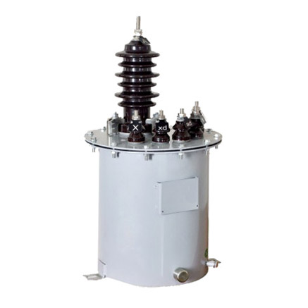
LB-10W 11kV Cast-Resin Current Transformer for Substation Metering and Protection – IEC 61869-2 Certified
Introduction to the LB-10W Current Transformer
The LB-10W is a high-reliability, cast-resin insulated current transformer (CT) engineered for accurate current measurement and robust protective relay coordination in 11kV (IEC-rated) or 10kV (domestic system) medium-voltage networks. Designed in strict accordance with IEC 61869-2 and GB/T 20840.2, this instrument transformer leverages advanced vacuum pressure impregnation (VPI) epoxy resin technology to deliver superior dielectric strength, environmental resilience, and long-term operational stability.
Operating Principle of Cast-Resin Insulation
Cast-resin insulation in the LB-10W employs a thermosetting epoxy compound that fully encapsulates the primary conductor, secondary windings, and magnetic core under vacuum conditions. This process eliminates air voids and moisture ingress pathways, resulting in a homogeneous dielectric structure with high partial discharge inception voltage (>20 kV at 1.2/50 µs impulse). The VPI technique ensures complete penetration into winding interstices, providing mechanical rigidity and thermal conductivity (0.2–0.3 W/m·K) that facilitates heat dissipation during overload conditions. Unlike oil-filled alternatives, the solid resin matrix eliminates fire hazards, leakage risks, and maintenance-intensive fluid monitoring, making it ideal for indoor switchgear and densely populated urban substations.
Advantages Over Oil-Immersed Designs
Compared to traditional oil-immersed CTs, the LB-10W offers significant operational and safety benefits. Its dry-type construction eliminates flammability concerns (compliant with IEC 60695 flammability tests), reduces weight by approximately 30%, and enables vertical or horizontal mounting without orientation constraints. The absence of oil also removes the need for conservator tanks, breather systems, and periodic oil sampling—critical for reducing lifecycle costs in remote or unmanned substations. Furthermore, the cast-resin body exhibits excellent UV and ozone resistance, ensuring stable performance in outdoor environments up to 40°C ambient temperature and 95% relative humidity. Thermal class F (155°C) insulation allows continuous operation at 1.2× rated current without degradation.
Typical Applications Overview
The LB-10W is deployed across diverse power infrastructure segments requiring precise current transformation for revenue metering and fault detection. Primary use cases include ring main units (RMUs), gas-insulated switchgear (GIS) interfaces, and pad-mounted transformers in distribution networks. Its compact dimensions (typically 220 mm height × 180 mm width) facilitate retrofitting into legacy 10kV panels originally designed for older CT models. The dual-core configuration—common in variants like LB-10W-2—supports simultaneous metering (0.5S class) and protection (5P10 or 5P20) functions, eliminating the need for separate transformers and reducing secondary wiring complexity.
Technical Specifications
The LB-10W adheres to stringent electrical and mechanical parameters defined by international and domestic standards. Below is a representative specification table for standard configurations:
| Parameter | Value |
|---|---|
| Rated Voltage (Ur) | 11 kV (IEC) / 10 kV (GB) |
| System Frequency | 50 Hz or 60 Hz |
| Primary Current (Ipr) | 50 A to 3000 A (standard steps) |
| Secondary Current (Isr) | 1 A or 5 A |
| Accuracy Class (Metering) | 0.2S, 0.5S per IEC 61869-2 |
| Accuracy Class (Protection) | 5P10, 5P15, 5P20 |
| Rated Output (Burden) | 5 VA to 30 VA (at cos φ = 0.8 lag) |
| Short-Time Thermal Current | 20×Ipr for 1 s (e.g., 60 kA for 3000 A primary) |
| Dynamic Withstand Current | 50×Ipr peak (e.g., 150 kA for 3000 A primary) |
| Insulation Level (LI/AC) | 75 kV LI / 28 kV AC (1 min) |
| Partial Discharge | <10 pC at 1.2×Ur/√3 |
| Ambient Temperature Range | −25°C to +40°C |
| Altitude Limit | ≤1000 m above sea level (derating required above) |
Standard Service Conditions
The LB-10W is rated for normal service conditions as defined in IEC 61869-1: ambient temperature between −25°C and +40°C, daily average not exceeding +35°C; relative humidity up to 95% with condensation; and installation altitude not exceeding 1000 meters. For installations above 1000 m, the dielectric withstand voltage must be derated by 1% per 100 m increment above baseline. The transformer is suitable for both indoor and outdoor applications when housed in IP23-rated enclosures. Pollution degree is classified as PD III (medium conductivity dust, temporary condensation), necessitating creepage distance of ≥20 mm/kV (phase-to-ground).
Core and Winding Configuration
Each LB-10W unit incorporates grain-oriented electrical steel (GOES) laminations with thickness of 0.23–0.27 mm and core loss ≤0.9 W/kg at 1.7 T, 50 Hz. The magnetic circuit is optimized to minimize remanence and hysteresis error, critical for protection-class accuracy during DC offset transients. Secondary windings are wound with electrolytic-tough-pitch (ETP) copper, insulated with Class F (155°C) enamel, and embedded within the resin matrix to prevent movement under electromagnetic forces. Terminal blocks feature tinned copper studs with M6 or M8 threads, rated for 130°C continuous operation and compatible with standard ring lugs (max. 25 mm² cross-section).
Typical Applications
The LB-10W’s design versatility supports deployment across modern power systems where reliability, accuracy, and space efficiency are paramount.
Substation Secondary Metering
In 11kV/10kV distribution substations, the LB-10W provides Class 0.5S or 0.2S current signals to revenue-grade energy meters (e.g., IEC 62053-22 compliant devices). Its low phase displacement error (<±10 minutes at 1–120% Ipr) ensures compliance with billing accuracy requirements. For example, in a 10 MVA urban substation feeding commercial loads, two LB-10W units (one per phase) supply inputs to a three-phase kWh meter, enabling precise demand profiling and loss allocation. The cast-resin housing resists electromagnetic interference from adjacent switchgear, maintaining signal integrity even during capacitor bank switching transients.
Industrial Power Distribution
Heavy industrial facilities—such as steel mills, chemical plants, and data centers—utilize the LB-10W for feeder monitoring and motor protection. In a typical 10kV motor control center (MCC), an LB-10W with 5P20 protection class feeds a digital relay (e.g., SEL-751) to detect phase-to-phase faults within 20 ms. The transformer’s high saturation point (≥20×Ipr) prevents core saturation during motor inrush currents (typically 6–8× full-load current), ensuring reliable trip coordination. Its compact form factor allows integration into space-constrained switchboards without compromising arc-flash safety distances.
Renewable Energy Integration
Solar photovoltaic (PV) and wind farms employ the LB-10W at the point of interconnection (POI) to grid-tie inverters or step-up transformers. For a 5 MW solar farm connected to an 11kV utility feeder, LB-10W CTs monitor export/import power flow for net metering and anti-islanding protection. The low burden requirement (as low as 2.5 VA at 5 A secondary) minimizes voltage drop across long cable runs to the SCADA RTU, preserving measurement fidelity. Additionally, the transformer’s immunity to DC bias—critical in inverter-based resources—ensures stable operation during asymmetric fault conditions.
Rural and Suburban Distribution Networks
In rural electrification projects, the LB-10W’s maintenance-free design reduces operational expenditure in hard-to-access locations. Mounted on pole-top reclosers or sectionalizers, it enables automated fault location, isolation, and service restoration (FLISR) via communication-enabled relays. For instance, a 10kV overhead line serving agricultural loads uses LB-10W CTs with 5P10 class to distinguish between temporary tree contact faults and permanent cable damage, minimizing unnecessary outages. The UV-stabilized resin housing withstands decades of direct sunlight exposure without cracking or tracking.
Compliance with International Standards
The LB-10W is certified to meet the rigorous requirements of both global and Chinese national standards, ensuring interoperability and regulatory acceptance.
IEC 61869-2 Compliance Details
IEC 61869-2:2012 (“Instrument transformers – Part 2: Additional requirements for current transformers”) governs the LB-10W’s design, testing, and marking. Key compliance aspects include: definition of rated primary current (Ipr) and secondary current (Isr); specification of composite error limits for protection classes (e.g., ≤10% error at 10×Ipr for 5P10); and mandatory short-circuit withstand capability verification. The standard also mandates clear labeling of accuracy class, rated output, and polarity markings (P1/P2, S1/S2) per IEC 60044-1 legacy conventions. All LB-10W units undergo type tests—including temperature rise, short-circuit, and impulse withstand—at accredited laboratories prior to certification.
Alignment with GB/T 20840.2
GB/T 20840.2-2014 (“Instrument transformers – Part 2: Current transformers”) mirrors IEC 61869-2 but includes China-specific provisions. Notably, GB/T requires additional seismic testing (horizontal acceleration 0.3g) for transformers installed in earthquake-prone regions like Sichuan Province. It also specifies tighter tolerance on ratio error for metering classes (±0.2% for 0.2S at 100% Ipr vs. IEC’s ±0.25%). The LB-10W meets both standards simultaneously through dual-certification, allowing seamless deployment in domestic Chinese grids and export markets. Markings include both “Ur=11kV” (IEC) and “Um=12kV” (GB system maximum voltage) to reflect regional nomenclature differences.
Testing and Certification Requirements
Certification involves three test categories: type tests (performed once per design), routine tests (100% production), and special tests (customer-requested). Type tests include power frequency withstand (28 kV rms, 1 min), lightning impulse (75 kV peak, 1.2/50 µs), and temperature rise (Δθ ≤60 K for windings). Routine tests encompass ratio verification (±0.1% tolerance), polarity check, and insulation resistance (>1000 MΩ at 2500 V DC). Certificates issued by bodies such as CEPREI (China) or KEMA (Netherlands) validate compliance.
On-Site Testing Procedures
Post-installation verification ensures the LB-10W performs within specified tolerances under actual operating conditions.
Insulation Resistance Test
Conducted using a 2500 V DC megohmmeter between primary-to-secondary, primary-to-ground, and secondary-to-ground circuits. Acceptance criterion: insulation resistance ≥1000 MΩ at 20°C. Values below 500 MΩ indicate moisture ingress or resin degradation. Temperature correction is applied using RT = R20 × 2(20−T)/10. This test must precede any high-voltage energization to prevent flashover.
Turns Ratio Test
Performed with a dedicated CT analyzer (e.g., Omicron CT Analyzer) injecting 1–10 A into the primary while measuring secondary current. The measured ratio must fall within ±0.1% of the nameplate value for metering classes and ±0.5% for protection classes. For a 600/5 A LB-10W, acceptable secondary current at 6 A primary is 49.95–50.05 mA. Deviations suggest winding shorts or incorrect tap selection.
Polarity Test
Verifies reducing polarity (standard for IEC CTs): when instantaneous current enters P1, it exits S1. Using a 9 V battery and analog ammeter, connect (+) to P1 and (−) to P2; momentary deflection of the ammeter needle toward positive scale when S1 is connected to (+) confirms correct polarity. Reversed polarity causes 180° phase shift, leading to false tripping in differential protection schemes.
Power Frequency Withstand Voltage Test
Applies 28 kV rms (50 Hz) for 1 minute between primary and grounded secondary/core. Leakage current must remain <1 mA. This test validates dielectric integrity after transportation-induced microcracks. Performed only during commissioning or after major maintenance; repeated testing accelerates insulation aging.
Excitation (Saturation) Characteristic Test
Measures secondary excitation voltage versus magnetizing current to determine knee-point voltage (Vk). For a 5P20 LB-10W, Vk must exceed 20×(Isr×Zb + Rct), where Zb is burden impedance and Rct is winding resistance. Example: with 5 A secondary, 15 VA burden (Zb=0.6 Ω), and Rct=0.3 Ω, Vk > 20×5×(0.6+0.3)=90 V. A low Vk indicates core saturation risk during faults.
Preventive Maintenance Guide
Although cast-resin CTs require minimal maintenance, scheduled inspections extend service life beyond 30 years.
Periodic Inspection Protocol
Annual visual checks include: examining resin surface for cracks, tracking, or discoloration; verifying terminal tightness (torque: 8–10 N·m for M6); and inspecting secondary wiring for insulation brittleness. In coastal areas, salt deposits on the housing should be cleaned with deionized water to prevent surface leakage currents. Thermographic scans during peak load can detect abnormal heating at terminals (>10 K above ambient warrants investigation).
Maintenance Intervals and Fault Diagnosis
A structured 5-year maintenance cycle includes retesting insulation resistance and ratio accuracy. Common failure modes and diagnostics:
- Ratio drift: Caused by partial winding shorts; confirmed via excitation test showing reduced Vk.
- High excitation current: Indicates core lamination damage; Vk drops by >15% from baseline.
- Moisture ingress: Evidenced by insulation resistance <200 MΩ and elevated tan δ (>0.5% at 10 kV).
Replacement is recommended if any parameter deviates beyond repairable limits.
| Maintenance Interval | Activities |
|---|---|
| Annual | Visual inspection, terminal torque check, thermography |
| 5 Years | Insulation resistance, ratio test, excitation curve |
| 10 Years | Full dielectric tests (if in harsh environment) |
Conclusion
The LB-10W 11kV cast-resin current transformer represents a benchmark in medium-voltage instrumentation, combining IEC 61869-2 and GB/T 20840.2 compliance with field-proven reliability. Its VPI epoxy resin encapsulation eliminates the operational hazards and maintenance burdens associated with oil-filled designs, while the GOES silicon steel core ensures metrological precision across metering (0.2S/0.5S) and protection (5P10–5P20) applications. With a rated thermal short-circuit withstand of 20×Ipr for 1 second and dynamic withstand up to 50×Ipr, the LB-10W delivers robust performance during grid disturbances. Designed for ambient temperatures from −25°C to +40°C and altitudes up to 1000 m, it adapts seamlessly to urban substations, industrial plants, renewable energy sites, and rural distribution networks. Adherence to strict manufacturing tolerances—evidenced by ratio error within ±0.1% and partial discharge below 10 pC—guarantees decades of maintenance-free service. When installed and tested per the procedures outlined herein, the LB-10W achieves an expected service life of 25–30 years, making it a cost-effective, future-proof solution for modern power systems demanding accuracy, safety, and longevity.
Q1: Can the LB-10W operate on a 10kV system despite its 11kV IEC rating?
Yes. The 11kV rating per IEC 61869-2 corresponds to the highest system voltage (Um = 12kV), making it fully compatible with nominal 10kV networks commonly used in China and other regions. The insulation level (28 kV AC withstand) exceeds the requirements for 10kV systems (typically 24 kV AC).
Q2: What is the maximum secondary burden for a 5P20 protection class?
The maximum burden depends on the specific ratio and core design. For a 600/5 A LB-10W-5P20, the maximum total burden (including lead resistance) is typically 4 Ω (100 VA at 5 A). Always consult the manufacturer’s excitation curve to verify Vk sufficiency.
Q3: Is the LB-10W suitable for outdoor installation without an enclosure?
No. While the cast-resin body is weather-resistant, terminals and secondary connections require protection from direct rain and contamination. Installation in an IP23 or higher rated enclosure is mandatory per IEC 61869-1.
Q4: How does temperature affect ratio error?
Ratio error varies by ≤±0.05% over the −25°C to +40°C range due to low thermal expansion coefficient of epoxy resin (60–80 ×10⁻⁶/°C) and stable GOES permeability. Calibration certificates account for this drift.
Q5: Can multiple secondary windings share the same core?
No. Each accuracy class (e.g., 0.5S metering and 5P20 protection) requires a dedicated magnetic core to prevent mutual interference during fault conditions. The LB-10W-2 model features two physically separated cores within one housing.