Contenido del artículo
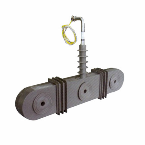
ZW-10 11kV Cast-Resin Current Transformer for Substation Metering and Protection – IEC 61869-2 Certified
Introduction to the ZW-10 Current Transformer
The ZW-10 is a high-reliability, dry-type current transformer (CT) engineered for critical metering and protection functions in 11kV (IEC-rated) or 10kV (domestic system equivalent) power distribution networks. Utilizing advanced vacuum pressure impregnation (VPI) cast-resin insulation technology, the ZW-10 eliminates the fire hazards, environmental risks, and maintenance burdens associated with traditional oil-immersed designs. Its robust construction ensures stable performance under demanding electrical and environmental conditions, making it ideal for both indoor switchgear and outdoor substation installations.
Operating Principle of Cast-Resin Insulation
Cast-resin insulation in the ZW-10 employs a cycloaliphatic epoxy resin system processed under vacuum and pressure to fully impregnate the wound secondary coil and encapsulate the grain-oriented electrical steel (GOES) core. This VPI technique eliminates air voids and moisture ingress pathways, resulting in superior dielectric strength and partial discharge resistance. The resin matrix provides mechanical rigidity, thermal stability up to 130°C continuous operation, and excellent tracking resistance (CTI > 600 V). Unlike oil-filled units, the solid dielectric offers no risk of leakage, requires no periodic oil testing, and maintains consistent insulation properties over decades of service. The homogeneous structure also minimizes thermal expansion mismatches, reducing long-term mechanical stress on internal components.
Advantages Over Oil-Immersed Designs
Compared to conventional oil-insulated CTs, the ZW-10 cast-resin design delivers significant operational and safety benefits. It is inherently fire-resistant (meeting IEC 60695 flammability requirements), eliminating explosion hazards in confined spaces like indoor substations or commercial buildings. Environmental compliance is simplified as there are no PCBs or hydrocarbon fluids requiring containment or disposal. Maintenance costs are drastically reduced—no oil sampling, degassing, or bushing inspections are needed. The compact form factor allows for easier integration into modern metal-enclosed switchgear, while the lighter weight simplifies handling and installation. Additionally, cast-resin CTs exhibit lower susceptibility to moisture-induced degradation, ensuring stable ratio and phase angle accuracy throughout their service life.
Typical Applications Overview
The ZW-10 is deployed across diverse medium-voltage infrastructure where precision measurement and dependable fault detection are paramount. Primary applications include revenue metering at utility interconnection points, protective relaying for feeders and transformers in 11kV/10kV substations, and monitoring in industrial plant distribution systems. Its dual-winding configuration supports simultaneous connection to metering (e.g., 0.5 class) and protection (e.g., 5P10) circuits without cross-interference. The unit’s robustness also makes it suitable for harsh environments such as coastal areas (with salt fog resistance per IEC 60068-2-52) and high-altitude locations (up to 3000 m above sea level with derating).
Technical Specifications
The ZW-10 adheres strictly to IEC 61869-2 and GB/T 20840.2 standards, with verified performance parameters ensuring interoperability and reliability in global power systems.
| Parameter | Value |
|---|---|
| Rated Voltage (Ur) | 11 kV (IEC) / 10 kV (Domestic) |
| System Frequency | 50/60 Hz |
| Primary Current Ratings | 50 A to 3150 A (standard); custom ratios available |
| Secondary Current | 1 A or 5 A |
| Accuracy Classes | Metering: 0.2S, 0.5S, 1; Protection: 5P10, 5P15, 5P20 |
| Rated Output (Burden) | 2.5 VA to 30 VA per winding (at rated current and accuracy class) |
| Short-Time Thermal Current (Ith) | 20×In for 1 s (e.g., 63 kA for 3150 A primary) |
| Dynamic Withstand Current (Idyn) | 2.5×Ith peak (e.g., 157.5 kA peak) |
| Insulation Level (LI/AC) | 75 kV lightning impulse / 28 kV power frequency (1 min) |
| Partial Discharge | <10 pC at 1.2×Ur/√3 |
| Ambient Temperature Range | –25°C to +40°C (–40°C optional) |
| Relative Humidity | Up to 95% non-condensing |
| Altitude | ≤1000 m standard; ≤3000 m with voltage derating per IEC 60071-2 |
| Core Material | Grain-Oriented Electrical Steel (GOES), M4 grade or better |
| Insulation System | VPI cycloaliphatic epoxy resin, Class F (155°C) |
Standard Service Conditions
The ZW-10 is rated for continuous operation under IEC 61869-1 standard service conditions: ambient temperature from –25°C to +40°C, daily average not exceeding +35°C. For cold-climate deployments (e.g., northern Europe or high-altitude sites), an extended low-temperature option (–40°C) is available, featuring modified resin formulation to prevent embrittlement. Humidity tolerance extends to 95% relative humidity without condensation, validated through 28-day damp heat testing per IEC 60068-2-78. At altitudes above 1000 m, the power frequency withstand voltage must be reduced by 1% per 100 m increment above 1000 m, as specified in IEC 60071-2. These derating factors ensure dielectric integrity remains uncompromised in mountainous or plateau regions.
Electrical Performance Tolerances
Ratio error and phase displacement are tightly controlled per IEC 61869-2. For a 0.5S class metering winding, ratio error must not exceed ±0.5% and phase error ±15 minutes at 100% In. Protection windings (5P10) guarantee composite error ≤5% at 10×In with rated burden. Burden tolerance is ±10% of stated VA rating. Short-circuit performance is validated through thermal and dynamic tests: the unit must withstand 20×In for 1 second without damage, and the peak electrodynamic force during a 2.5×Ith fault must not cause mechanical deformation exceeding 0.5 mm at terminal connections. These stringent tolerances ensure compatibility with modern digital relays and smart meters requiring high-fidelity current signals.
Typical Applications
The ZW-10’s dual functionality enables deployment across utility, industrial, and renewable sectors where accuracy and reliability are non-negotiable.
Substation Secondary Metering
In 11kV/10kV distribution substations, the ZW-10 provides revenue-grade current signals to billing meters. Its 0.2S or 0.5S accuracy class meets IEC 62053-22 requirements for fiscal metering, even at low load currents (down to 1% In for 0.2S). The cast-resin housing resists electromagnetic interference from adjacent switchgear, ensuring signal integrity. For example, in a European urban substation feeding commercial districts, ZW-10 units with 600/5 A, 0.2S/5P10 dual windings supply data to AMI systems while simultaneously tripping circuit breakers during feeder faults. The absence of oil eliminates contamination risks in indoor GIS installations.
Industrial Power Distribution
Heavy industries—such as steel mills, chemical plants, and data centers—rely on the ZW-10 for motor protection and energy management. In a 10kV motor control center (MCC), ZW-10 CTs with 5P20 protection windings detect locked-rotor or phase-loss conditions within milliseconds, preventing catastrophic motor damage. Simultaneously, the 1.0 class metering winding feeds real-time energy consumption data to SCADA systems for load profiling. The unit’s high short-circuit withstand (e.g., 63 kA for 3150 A models) handles the intense fault currents typical of industrial networks with low source impedance.
Renewable Energy Integration
Solar farms and wind parks utilize ZW-10 CTs at the point of interconnection (POI) to grid operators. Here, the CT must accurately measure bidirectional power flow for net metering while providing fast fault detection to isolate islanding events. The ZW-10’s linear response across 1–120% In ensures precise measurement during variable renewable output, and its immunity to DC offset (from inverter harmonics) prevents saturation during asymmetrical faults. In a 20 MW solar farm in Spain, ZW-10 units with 1200/1 A ratios interface with IEC 61850-compliant relays for anti-islanding protection, meeting ENTSO-E grid code requirements.
Rural and Suburban Distribution Networks
For utilities managing extensive rural feeders, the ZW-10’s maintenance-free design reduces operational expenditure. Mounted on pole-top reclosers or pad-mounted transformers, these CTs endure temperature swings from –30°C to +50°C and resist UV degradation thanks to UV-stabilized resin. Their compact size fits legacy infrastructure without costly retrofits. In Southeast Asian microgrids, ZW-10 units enable accurate loss allocation between villages by metering branch currents with 0.5S accuracy, while 5P10 windings coordinate with sectionalizers to minimize outage duration during tree-contact faults.
Compliance with International Standards
The ZW-10 is engineered to satisfy both global and regional regulatory frameworks, ensuring seamless integration into international projects.
IEC 61869-2 Certification Details
IEC 61869-2 governs instrument transformer performance, safety, and testing. The ZW-10 complies with all mandatory clauses, including: insulation coordination (Section 5), accuracy requirements (Section 6), thermal and dynamic withstand (Section 7), and type tests (Section 8). Critical validations include power frequency withstand (28 kV for 1 min), lightning impulse (75 kV positive/negative), and partial discharge (<10 pC). Accuracy verification follows IEC 61869-6 procedures using calibrated reference standards traceable to national labs. Each production batch undergoes routine tests per Section 9, including ratio, polarity, and insulation resistance checks. Third-party certification by accredited bodies (e.g., KEMA, CESI) confirms full compliance.
GB/T 20840.2 Alignment for Domestic Markets
For Chinese and other markets adopting GB standards, the ZW-10 aligns with GB/T 20840.2 (equivalent to IEC 61869-2 but with localized nuances). Key differences include: GB specifies 10kV as nominal system voltage (vs. IEC’s 11kV), though insulation levels remain identical (75/28 kV). Accuracy classes use identical notation (0.2S, 5P10), but GB mandates additional short-time current tests at 40×In for 1 s in some industrial applications. The ZW-10 meets these via reinforced core clamping and optimized resin fill density. All units destined for China carry CMA/CNAS-accredited test reports verifying GB compliance, facilitating rapid grid approval.
Testing and Certification Requirements
Type testing per IEC 61869-2 includes 15+ rigorous procedures: temperature rise (Δθ ≤ 55 K for windings), short-circuit (thermal/dynamic), impulse, wet test (for outdoor types), and seismic (if applicable). Routine tests on every unit cover: visual inspection, power frequency withstand (80% of type test value), ratio/polarity, and insulation resistance (>1000 MΩ at 2500 V DC). Sample tests (per batch) include partial discharge and accuracy verification. Certificates of Conformity reference test reports with unique serial numbers, enabling full traceability.
On-Site Testing Procedures
Post-installation verification ensures the ZW-10 performs as specified under field conditions. All tests follow IEC 61869-10 guidelines.
Insulation Resistance Test
Measure insulation resistance between primary-secondary and primary-ground using a 2500 V DC megohmmeter. Connect all secondary terminals together and to ground. Apply voltage for 1 minute. Acceptance criterion: ≥1000 MΩ at 20°C. Correct for temperature using RT2 = RT1 × 2(T1–T2)/10. Low readings indicate moisture ingress or resin cracking—requiring drying or replacement. This test is critical after transportation in humid climates.
Turns Ratio Test
Use a dedicated CT analyzer (e.g., Omicron CT Analyzer) applying 1–5 V AC to secondary winding. Measure induced primary voltage. Calculate ratio as Vsec/Vprim. Compare to nameplate (e.g., 600:5 = 120:1). Tolerance: ±0.2% for metering, ±0.5% for protection classes. Deviations >1% suggest turn-to-turn shorts or incorrect tap selection. Always demagnetize core before testing to avoid hysteresis errors.
Polarity Test
Verify reducing polarity per IEC 61869-1. Apply 1.5–3 V DC to primary (P1 to P2). Momentarily connect; observe secondary voltage spike direction with oscilloscope or analog voltmeter. Positive deflection at S1 (when P1 is positive) confirms correct polarity. Incorrect polarity causes relay misoperation—e.g., directional overcurrent elements tripping for reverse power flow. This test is mandatory before energizing protection circuits.
Power Frequency Withstand Voltage Test
Apply 28 kV RMS (for 11kV class) at 50 Hz between primary-ground and primary-secondary for 1 minute. Use a calibrated test transformer with overcurrent trip (≤100 mA). No flashover or disruptive discharge permitted. For field tests, reduce to 80% (22.4 kV) if equipment limitations exist. Ensure secondary windings are short-circuited and grounded during test to prevent dangerous overvoltages.
Short-Circuit Test (for CTs)
Unlike VTs, CTs require short-circuit validation. Inject 10–20× rated current (e.g., 12 kA for 600 A CT) for 1–3 seconds using a portable fault simulator. Monitor secondary waveform for distortion indicating core saturation. Post-test, recheck ratio and insulation resistance. Significant deviation suggests mechanical damage to windings or core laminations. This test is recommended after severe system faults to confirm CT integrity.
Preventive Maintenance Guide
While cast-resin CTs require minimal upkeep, scheduled inspections extend service life and prevent unexpected failures.
Periodic Inspection Protocol
Conduct annual visual and electrical checks: inspect housing for cracks, discoloration, or tracking marks; clean surface with dry cloth (no solvents); verify terminal tightness (torque: 12 N·m for M8 bolts); measure insulation resistance. After severe weather (lightning, flooding), perform immediate post-event inspection. In polluted environments (e.g., cement plants), increase frequency to semi-annual. Document findings in asset management systems to trend degradation.
Maintenance Intervals and Fault Diagnosis
Table: Recommended Maintenance Schedule
| Interval | Actions |
|---|---|
| Annual | Visual inspection, IR thermography (hot spots >10°C above ambient indicate loose connections), insulation resistance test |
| 5-Year | Full electrical test suite (ratio, polarity, burden verification), partial discharge scan if available |
| Post-Fault | Short-circuit test, core remanence check, physical integrity assessment |
Common faults include: open secondary circuit (causes dangerous overvoltage—always short before disconnecting), core saturation (from excessive DC offset), and terminal corrosion (in coastal areas). Diagnose via abnormal relay behavior or meter drift. Replace if insulation resistance drops below 500 MΩ persistently after cleaning/drying.
Conclusion
The ZW-10 11kV cast-resin current transformer represents the convergence of material science, precision engineering, and international standardization for modern power systems. By leveraging VPI epoxy resin encapsulation and GOES cores, it delivers unmatched safety, accuracy, and longevity compared to legacy oil-filled alternatives. Its dual compliance with IEC 61869-2 and GB/T 20840.2 ensures global applicability—from European smart grids to Chinese industrial complexes—without compromising performance. Rigorous type testing validates its ability to withstand extreme electrical stresses, while minimal maintenance requirements reduce total cost of ownership over a projected service life of 25–30 years. In an era demanding grid resilience and measurement fidelity, the ZW-10 provides a future-proof solution for critical metering and protection functions at the 11kV level. Utilities and engineers can deploy it with confidence, knowing it meets the highest benchmarks for reliability, safety, and technical excellence in instrument transformer technology.
Q1: Can the ZW-10 operate at 12kV system voltage?
No. The ZW-10 is rated for 11kV maximum system voltage per IEC 61869-2. Operating above Ur violates insulation coordination and voids certification. For 12kV systems, select a 12kV-class CT (e.g., ZW-12).
Q2: What is the maximum altitude rating without derating?
1000 meters above sea level. Above this, reduce power frequency withstand voltage by 1% per 100 m increment per IEC 60071-2.
Q3: Is the ZW-10 suitable for indoor GIS applications?
Yes. Its compact, oil-free design is ideal for gas-insulated switchgear. Ensure creepage distance meets pollution degree 3 requirements (≥25 mm/kV).
Q4: How to handle secondary open-circuit during maintenance?
Always short-circuit secondary terminals with a dedicated shorting link before disconnecting loads. An open secondary can generate lethal voltages (>3 kV) during primary current flow.
Q5: What accuracy class is required for revenue metering?
IEC 62053-22 mandates 0.2S or 0.5S for fiscal metering. The ZW-10 offers both, with 0.2S providing superior low-load accuracy (down to 1% In).
Q6: Does the ZW-10 require periodic recalibration?
No. Cast-resin CTs exhibit negligible aging-related drift. Recalibration is only needed after physical damage or failed routine tests.
Q7: Can multiple secondary windings share a common core?
Yes. The ZW-10 uses a single GOES core with bifilar-wound secondaries, ensuring magnetic coupling without cross-talk between metering and protection circuits.