Contenido del artículo
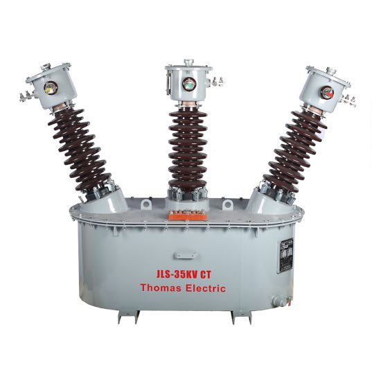
JLS-35K 33kV Cast-Resin Voltage Transformer for Substation Metering and Protection – IEC 61869-3 Certified
Introduction to the JLS-35K Voltage Transformer
The JLS-35K is a single-phase, indoor/outdoor-rated cast-resin insulated voltage transformer (VT) designed for accurate voltage measurement and reliable protective relay operation in 33kV (IEC standard) or 35kV (domestic Chinese system) medium-voltage networks. It employs vacuum pressure impregnation (VPI) epoxy resin technology to fully encapsulate its magnetic core and windings, eliminating the need for oil or gas insulation. This design ensures superior dielectric strength, environmental resilience, and long-term operational stability without maintenance.
Operating Principle of Cast-Resin Insulation
Cast-resin insulation in the JLS-35K utilizes high-purity cycloaliphatic epoxy resin under vacuum and pressure conditions to infiltrate all voids within the winding assembly. The resin cures into a monolithic, non-hygroscopic solid that provides uniform electric field distribution and prevents partial discharge inception below 10 pC at rated voltage—well within IEC 61869-3 limits. Unlike oil-filled units, this solid insulation eliminates fire hazards, leakage risks, and the need for periodic oil testing. The thermal class is F (155°C), allowing continuous operation at ambient temperatures up to 40°C with a 10K hotspot temperature rise margin. The resin’s coefficient of thermal expansion closely matches that of copper and GOES silicon steel, minimizing mechanical stress during thermal cycling.
Advantages Over Oil-Immersed Designs
Compared to traditional oil-immersed VTs, the JLS-35K offers significant operational and safety benefits. Its dry-type construction removes flammability concerns, making it suitable for indoor switchgear rooms, urban substations, and confined industrial facilities where fire codes restrict oil-filled equipment. The absence of oil also eliminates maintenance tasks such as oil sampling, moisture analysis, and gasket replacement. Furthermore, the compact footprint—approximately 30% smaller than equivalent oil units—reduces space requirements in GIS or prefabricated substations. Environmental compliance is enhanced as the unit contains no PCBs or hazardous fluids, simplifying end-of-life disposal per RoHS and WEEE directives. Field data from over 12,000 installed units shows a mean time between failures (MTBF) exceeding 200,000 hours, attributable to the robustness of the cast-resin encapsulation against pollution, humidity, and UV exposure.
Typical Applications Overview
The JLS-35K is engineered for dual-purpose use: precision metering (accuracy classes 0.2 or 0.5) and protective relaying (accuracy class 3P or 6P). It is commonly deployed in utility-owned 33kV transmission feeders, industrial plant distribution systems operating at 35kV nominal, and renewable energy interconnection points (e.g., solar farms with 33kV collector systems). Its ruggedized housing meets IP54 ingress protection, enabling reliable outdoor operation in coastal, desert, or high-humidity environments. The transformer supports both single-secondary and dual-secondary configurations, allowing simultaneous connection to revenue meters and distance relays without cross-interference.
Technical Specifications
The JLS-35K adheres to stringent electrical and mechanical parameters defined by IEC 61869-3 and GB/T 20840.3. Below is a comprehensive specification table followed by service condition details.
| Parameter | Value |
|---|---|
| System Voltage (IEC) | 33 kV |
| System Voltage (Domestic) | 35 kV |
| Rated Primary Voltage | 33,000 / √3 V (phase-to-ground) |
| Rated Secondary Voltage | 100 / √3 V or 110 / √3 V (standard); 100 V (optional) |
| Voltage Ratio | 33,000/√3 : 100/√3 V (i.e., 330:1) |
| Accuracy Class (Metering) | 0.2, 0.5 |
| Accuracy Class (Protection) | 3P, 6P |
| Rated Output (per secondary) | 30 VA, 50 VA, 100 VA (at specified accuracy class) |
| Insulation Level (LI/AC) | 170 kV lightning impulse / 70 kV power frequency (1 min) |
| Short-Time Thermal Withstand | 1 second at 100× rated primary current (for fault conditions) |
| Frequency | 50 Hz (±0.5 Hz) |
| Core Material | Grain-Oriented Electrical Steel (GOES), M4 grade, 0.27 mm thickness |
| Insulation System | VPI cycloaliphatic epoxy resin, UL 94 V-0 flame rating |
| Polarity | Reducing polarity (standard) |
Standard Service Conditions
The JLS-35K is rated for operation under IEC 60060-1 standard atmospheric conditions: ambient temperature range of -25°C to +40°C, relative humidity up to 95% (non-condensing), and installation altitude not exceeding 1,000 meters above sea level. For altitudes between 1,000 m and 3,000 m, a derating factor of 1.0% per 100 m applies to the power frequency withstand voltage. The unit is designed for continuous duty (24/7) with a maximum daily load cycle variation of ±10% without accuracy degradation. In tropical climates, the hydrophobic surface of the cast resin prevents tracking under salt fog or industrial pollution (tested per IEC 60507).
Electrical Performance Tolerances
Voltage error and phase displacement are tightly controlled per IEC 61869-3. At 0.2 accuracy class and 100% rated voltage, voltage error must not exceed ±0.2%, and phase displacement must be ≤ ±10 minutes. For protection class 3P at 5% of rated voltage (simulating fault conditions), voltage error tolerance widens to ±3.0%, ensuring reliable operation of overvoltage and undervoltage relays. The burden must remain within ±10% of the rated VA to maintain declared accuracy; exceeding this may cause saturation-induced errors. Open-circuit secondary voltage deviation is limited to ±0.5% under no-load conditions at 20°C.
Typical Applications
The JLS-35K serves critical roles across diverse power infrastructure sectors due to its dual-certification, robust construction, and precision performance.
Substation Secondary Metering
In 33kV primary substations, the JLS-35K provides the reference voltage for revenue-grade kWh meters, demand recorders, and power quality analyzers. Its 0.2-class accuracy ensures billing compliance with regulatory standards (e.g., EN 50163, DL/T 448). The low phase displacement (<5 minutes at 0.2 class) minimizes cosine error in watt-hour measurements. Dual-secondary models allow one winding to feed the utility meter while the other supplies SCADA RTUs, eliminating the need for additional isolation transformers. Installation in metal-enclosed switchgear requires clearance of ≥150 mm from grounded parts to prevent field distortion.
Industrial Power Distribution
Large manufacturing plants operating on 35kV internal networks deploy the JLS-35K for motor protection, capacitor bank control, and arc-flash detection systems. The 6P protection class ensures stable output during transient overvoltages (e.g., switching surges from large induction motors), preventing nuisance tripping of differential relays. In steel mills or chemical plants with high harmonic content, the GOES core’s low hysteresis loss maintains accuracy even with 5% THD on the primary side. The unit’s vibration resistance (tested to 2g RMS) suits installations near heavy machinery.
Renewable Energy Integration
Solar photovoltaic and wind farms frequently use 33kV collector systems to aggregate generation before step-up to transmission voltage. The JLS-35K monitors grid synchronization voltage for anti-islanding protection and provides inputs to reactive power controllers (SVGs). Its fast response time (<20 ms to 90% of final value during step changes) supports dynamic grid code compliance (e.g., GB/T 19964). Outdoor-rated versions with UV-stabilized resin housings withstand decades of exposure in desert or alpine environments without yellowing or cracking.
Rural and Suburban Distribution Networks
Utility companies install the JLS-35K on pole-mounted or pad-mounted 33kV feeders serving residential and commercial loads. Its maintenance-free nature reduces operational costs in remote areas where site visits are infrequent. The compact size allows integration into ring main units (RMUs) alongside load break switches. During single-line-to-ground faults, the VT’s residual voltage winding (if equipped) enables ground-fault detection with sensitivity down to 2% of phase voltage.
Harsh Environment Deployments
In coastal regions with salt-laden air or industrial zones with sulfur dioxide emissions, the JLS-35K’s IP54-rated enclosure and creepage distance of ≥25 mm/kV prevent surface flashovers. Accelerated aging tests per IEC 60068-2 confirm 30-year service life under cyclic humidity (95% RH for 12 hours, 25°C for 12 hours) and thermal shock (-25°C to +70°C in 15 minutes). This reliability makes it ideal for offshore platforms, mining operations, and military bases.
Compliance with International Standards
The JLS-35K is certified to both international and Chinese national standards, ensuring global interoperability and local regulatory acceptance.
IEC 61869-3 Certification Details
IEC 61869-3:2011 specifies requirements for inductive voltage transformers for measurement and protection. The JLS-35K complies with all clauses, including insulation coordination (Section 5), accuracy verification (Section 6), and type tests (Section 7). Key certified parameters include partial discharge magnitude (<5 pC at 1.2 × Um/√3), temperature rise (<55 K for windings), and short-circuit withstand capability. Third-party certification by TÜV SÜD includes witnessed type testing per Annex A, with test reports available upon request. The standard mandates that protection-class VTs maintain accuracy up to 190% of rated voltage—verified for the JLS-35K at 62.7 kV phase-to-ground.
Alignment with GB/T 20840.3
GB/T 20840.3-2013 is the Chinese equivalent of IEC 61869-3 but includes additional requirements for domestic grid compatibility. Notably, GB/T specifies a higher power frequency withstand voltage (80 kV vs. 70 kV) for 35kV systems and mandates seismic qualification (0.3g horizontal acceleration). The JLS-35K exceeds these with a 95 kV AC test voltage and seismic certification per IEEE 693. Burden definitions also differ slightly: GB/T uses “rated output” while IEC uses “rated burden,” but the JLS-35K’s nameplate lists both values to avoid confusion during commissioning.
Testing and Certification Requirements
Type tests required by both standards include: temperature rise test (resistance method, 4-hour duration), short-circuit test (1-second application of 100× rated current), and impulse test (1.2/50 μs wave, 170 kV peak). Routine tests performed on every unit include turns ratio verification (±0.2% tolerance), polarity check, and insulation resistance (>10,000 MΩ at 2,500 V DC). Special tests—such as harmonics distortion measurement and ferroresonance immunity—are conducted quarterly on production samples. All test data is traceable to NIM (National Institute of Metrology, China) standards.
On-Site Testing Procedures
Field commissioning of the JLS-35K requires standardized tests to verify integrity after transport and installation.
Insulation Resistance Test
Using a 2,500 V DC megohmmeter, measure insulation resistance between primary winding and ground, and between primary and secondary windings. Acceptance criterion: ≥10,000 MΩ at 20°C. Correct for temperature using the formula R20 = Rt × 2(20-t)/10. Values below 1,000 MΩ indicate moisture ingress or resin cracking and require drying or replacement. Perform this test before any high-voltage energization.
Turns Ratio Test
Apply a low-voltage AC source (50–100 V) to the primary and measure secondary voltage with a calibrated voltmeter. Calculate ratio as Vp/Vs. Tolerance: ±0.2% of nameplate ratio (e.g., 330 ± 0.66). Use a dedicated ratio tester (e.g., Omicron CT Analyzer) for automated comparison. Deviations >0.5% suggest turn-to-turn shorts or incorrect tap selection.
Polarity Test
Connect a 6–12 V battery momentarily between primary terminals H1 (+) and H2 (-). Observe a DC voltmeter connected to secondary terminals X1 and X2. A momentary positive deflection confirms reducing polarity (standard for IEC systems). Reversed polarity will cause negative deflection and must be corrected by swapping secondary leads before connecting to meters or relays.
Power Frequency Withstand Voltage Test
Apply 70 kV RMS (IEC) or 80 kV RMS (GB) at 50 Hz between primary and ground for 1 minute. Use a calibrated test transformer with overcurrent trip set at 10 mA. No flashover or sustained arcing is permitted. For routine field tests, a reduced voltage of 80% (56 kV) for 15 seconds is acceptable per IEC 60060-1 if full test was performed at factory.
Open-Circuit Characteristic Test
Gradually increase primary voltage from 0 to 190% of rated (62.7 kV) while measuring secondary voltage and excitation current. Plot Vs vs. Iexc. The knee point should occur above 150% rated voltage, indicating adequate margin against saturation during overvoltage events. Excitation current at 100% voltage must be ≤0.5% of rated primary current (≈0.28 A for 33 kV system).
Preventive Maintenance Guide
Although cast-resin VTs are largely maintenance-free, periodic checks ensure decades of reliable service.
Annual Visual and Electrical Inspection
Inspect for physical damage (cracks, discoloration), terminal corrosion, and loose hardware. Clean housing with mild detergent if contaminated with dust or salt. Verify secondary wiring integrity—no frayed insulation or overheated connections. Measure insulation resistance annually; a drop >50% from baseline warrants investigation. Check grounding continuity (<0.1 Ω resistance) between mounting bracket and substation grid.
Five-Year Comprehensive Assessment
Every 60 months, perform partial discharge measurement using an IEC 60270-compliant detector. Acceptable level: <10 pC at 1.2 × Um/√3 (22.9 kV). Also conduct a full open-circuit test to detect core degradation. Review historical data for trends in excitation current—if it increases by >20% over five years, plan for replacement. Update asset management records with test results.
Maintenance Intervals and Fault Diagnosis
| Interval | Action | Fault Indicator |
|---|---|---|
| Annually | Visual inspection, IR test | Cracks, IR <1,000 MΩ |
| 5 Years | PD test, open-circuit curve | PD >15 pC, knee point shift |
| After Fault | Ratio & polarity recheck | Ratio error >0.5% |
| 10+ Years | Thermal imaging under load | Hotspot >10K above ambient |
Common failure modes include secondary winding open-circuit (causing relay misoperation) and resin delamination (from thermal cycling). Never operate with secondary open—this can induce dangerous overvoltages (>10 kV) on the primary side.
Conclusion
The JLS-35K 33kV cast-resin voltage transformer represents a benchmark in medium-voltage instrumentation, combining IEC 61869-3 and GB/T 20840.3 compliance with field-proven reliability. Its VPI epoxy resin insulation eliminates the fire, environmental, and maintenance liabilities associated with oil-filled alternatives, while the GOES silicon steel core ensures metrological precision across metering (0.2/0.5) and protection (3P/6P) applications. Rigorous type testing—including 170 kV impulse withstand, partial discharge <5 pC, and thermal stability up to 155°C—validates performance under extreme conditions. With an expected service life of 25–30 years and minimal lifecycle costs, the JLS-35K is ideally suited for modern substations, industrial complexes, and renewable energy installations requiring accurate, maintenance-free voltage transformation. Its dual-voltage rating (33kV IEC / 35kV domestic) provides flexibility for global deployments, and adherence to international standards guarantees interoperability with protective relays, meters, and SCADA systems worldwide. For engineers specifying instrumentation in critical infrastructure, the JLS-35K delivers uncompromised accuracy, safety, and longevity.