Article Content
IEC 61869-3 Certified 33kV Cast-Resin Voltage Transformer JDZW-35 for Metering & Protection Applications
Introduction to the JDZW-35 Voltage Transformer
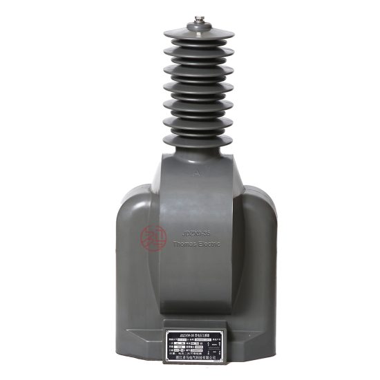
The JDZW-35 is a single-phase, outdoor-rated cast-resin voltage transformer (VT) designed for accurate voltage measurement and reliable protective relay operation in 33kV (IEC standard) or 35kV (Chinese domestic system) medium-voltage networks. It employs advanced vacuum pressure impregnation (VPI) epoxy resin technology to encapsulate its magnetic core and windings, providing superior dielectric strength, mechanical robustness, and environmental resistance compared to traditional oil-immersed designs.
Operating Principle of Cast-Resin Insulation
Cast-resin insulation in the JDZW-35 utilizes a two-component epoxy system applied under vacuum and pressure to fully impregnate the primary and secondary windings wound around a grain-oriented electrical steel (GOES) core. This process eliminates air voids and moisture ingress pathways, resulting in a homogeneous solid dielectric with high partial discharge inception voltage (>20 kV at 1.2 × Ur). The cured resin exhibits excellent thermal conductivity (0.8–1.2 W/m·K), enabling efficient heat dissipation during continuous operation at rated load. Unlike oil-filled units, cast-resin VTs are non-flammable, require no oil containment systems, and eliminate risks associated with oil leakage or degradation over time. The solid insulation also provides superior resistance to tracking and erosion under polluted or humid conditions, making it ideal for coastal or industrial environments.
Advantages Over Oil-Immersed Designs
The JDZW-35 offers significant operational and safety advantages over oil-immersed voltage transformers. First, it is maintenance-free—no oil sampling, level checks, or breather replacement is required throughout its service life. Second, its fire-resistant construction complies with IEC 60695 flammability standards, reducing fire hazards in indoor switchgear or densely populated substations. Third, the compact, sealed design prevents moisture absorption, ensuring stable dielectric properties even after decades of exposure. Additionally, the absence of liquid insulation eliminates environmental contamination risks during handling or end-of-life disposal. From an installation perspective, the lighter weight (typically 85–110 kg vs. 150+ kg for oil types) simplifies handling and reduces structural support requirements. Finally, the consistent thermal performance of epoxy resin minimizes ratio and phase angle errors across ambient temperature ranges from –40°C to +40°C.
Typical Applications Overview
The JDZW-35 is engineered for dual-purpose use in both revenue metering and protective relaying circuits within 33/35kV distribution and transmission infrastructure. Its accuracy class of 0.2/3P ensures precise energy billing while simultaneously supporting fast-acting overvoltage, undervoltage, and earth-fault protection schemes. Common deployment sites include utility-owned outdoor substations, industrial plant switchyards, wind and solar farm collector substations, and rural distribution feeders. The unit’s robust construction allows direct pole or platform mounting without additional enclosures, and its standardized secondary terminals (typically 1a–1n, da–dn) facilitate seamless integration with modern digital meters and IEDs (Intelligent Electronic Devices).
Technical Specifications
The JDZW-35 adheres to stringent electrical and mechanical parameters defined by IEC 61869-3 and GB/T 20840.3, ensuring interoperability and long-term reliability in demanding grid environments.
Rated Electrical Parameters
The primary rated voltage is 33 kV (line-to-earth), corresponding to a system voltage of 35 kV per Chinese GB standards. The standard secondary voltage is 100/√3 V for metering and 100 V for residual (open-delta) protection windings. Typical voltage ratios include 33,000/√3 : 100/√3 : 100 V. Accuracy classes are 0.2 for metering (burden ≤ 30 VA) and 3P for protection (burden ≤ 100 VA), with composite error limits of ±0.2% and ±3%, respectively, at 100% rated voltage. Rated outputs are 30 VA (0.2 class) and 100 VA (3P class). The insulation level meets IEC 60071-1 requirements: power frequency withstand voltage of 70 kV (rms, 1 min) and lightning impulse withstand voltage of 170 kV (peak, 1.2/50 μs). The maximum operating temperature rise is 60 K above ambient at rated load, verified per IEC 61869-3 thermal tests.
Environmental and Mechanical Ratings
The JDZW-35 is rated for outdoor installation with an IP54 ingress protection level. Standard service conditions include ambient temperature range of –40°C to +40°C, relative humidity up to 100% (condensing), and altitude ≤ 1,000 m above sea level. For installations above 1,000 m, derating factors apply per IEC 60071-2: insulation withstand voltages must be increased by 1% per 100 m above 1,000 m. The unit features M12 stainless steel mounting brackets and tinned copper secondary terminals rated for 600 V and 20 A continuous current. Creepage distance exceeds 25 mm/kV (minimum 825 mm for 33 kV), satisfying pollution severity class III per IEC 60815. The total mass is approximately 95 kg, with dimensions of 680 mm (H) × 320 mm (W) × 280 mm (D).
Core and Winding Construction
The magnetic circuit employs high-permeability grain-oriented electrical steel (GOES) laminations (M4 grade, 0.27 mm thickness), annealed to minimize hysteresis losses and ensure low excitation current (<0.5% of rated primary current at 1.9 × Ur). Primary windings consist of enameled copper wire with Class F (155°C) insulation, while secondary windings use double-insulated stranded copper conductors. Both windings are embedded in cycloaliphatic epoxy resin via VPI, achieving a partial discharge level <5 pC at 1.2 × Ur/√3. The core is clamped with non-magnetic stainless steel frames to suppress vibration-induced noise (<45 dB at 1 m distance). Thermal sensors (optional) can be embedded to monitor hotspot temperatures for predictive maintenance.
Typical Applications
The JDZW-35 serves critical roles across diverse power infrastructure sectors due to its dual accuracy classes and rugged construction.
Substation Secondary Metering
In 33kV utility substations, the JDZW-35 provides the reference voltage signal for revenue-class energy meters. Its 0.2 accuracy class ensures compliance with regulatory requirements for billing precision, even under light-load conditions (down to 25% of rated burden). The low phase angle error (<10 minutes at 100% load) minimizes reactive energy measurement inaccuracies. Units are typically installed on each phase of the busbar, with secondary outputs routed to a centralized metering panel. The cast-resin design eliminates oil-related maintenance, reducing lifecycle costs in unmanned or remote substations. Integration with AMI (Advanced Metering Infrastructure) systems is straightforward due to stable output characteristics over temperature and time.
Industrial Power Distribution Systems
Large manufacturing facilities often operate their own 35kV distribution networks. Here, the JDZW-35 supports both internal energy accounting and motor protection schemes. For example, in a steel mill, multiple JDZW-35 units feed voltage inputs to differential relays protecting 35kV induction motors. The 3P protection class guarantees reliable operation during transient overvoltages caused by capacitor bank switching. The non-flammable construction is particularly valuable in hazardous areas where fire codes restrict oil-filled equipment. Furthermore, the unit’s immunity to vibration makes it suitable for installation near heavy machinery.
Renewable Energy Integration
Wind and solar farms frequently use 33kV collector systems to aggregate power before step-up transformation. The JDZW-35 monitors grid voltage at the point of interconnection (POI) for anti-islanding protection and power quality compliance. Its fast response to voltage sags/swells enables timely disconnection per IEEE 1547 or GB/T 19964 requirements. In offshore wind platforms, the high creepage distance and hydrophobic resin surface resist salt fog corrosion. The VT’s ability to maintain accuracy under harmonic distortion (tested up to 5% THD) ensures reliable operation despite inverter-generated harmonics.
Rural and Suburban Distribution Networks
In rural electrification projects, the JDZW-35 is mounted on poles or pad-mounted transformers to provide voltage signals for feeder automation and fault location. Its lightweight design simplifies aerial installation using standard hot-stick tools. The wide temperature tolerance ensures reliable operation in extreme climates—from Siberian winters to Middle Eastern summers. Utilities benefit from reduced theft risk (no valuable oil) and lower inventory costs due to standardized design across multiple feeder types. The unit’s 25+ year service life aligns with long-term rural grid investment horizons.
Compliance with International Standards
The JDZW-35 is certified to both global and Chinese national standards, ensuring compatibility with international procurement specifications and domestic grid codes.
IEC 61869-3 Compliance Details
IEC 61869-3:2011 defines performance, testing, and marking requirements for inductive voltage transformers. The JDZW-35 meets all mandatory clauses, including accuracy verification at 80%, 100%, and 120% of rated voltage; temperature rise limits; short-circuit withstand capability (withstanding 100 × rated primary current for 1 s without damage); and electromagnetic compatibility (EMC) per IEC 61000-4 series. Type tests include power frequency and impulse withstand, partial discharge measurement (<10 pC at 1.2 × Ur), and thermal stability. Routine tests performed on every unit include turns ratio verification (±0.25% tolerance), polarity check, and insulation resistance (>10,000 MΩ at 2,500 V DC).
Alignment with GB/T 20840.3
GB/T 20840.3-2013 is China’s national adoption of IEC 61869-3, with minor modifications reflecting local grid practices. Key differences include the designation of 35kV as the nominal system voltage (vs. 33kV in IEC), slightly higher creepage distance requirements for pollution class III (≥31 mm/kV vs. 25 mm/kV), and mandatory seismic qualification for regions with seismic intensity ≥ VIII. The JDZW-35 is tested per GB/T 11022 for environmental endurance and GB/T 7595 for insulation coordination. All nameplate markings comply with GB/T 20840.1, including Chinese characters for model, ratio, and accuracy class.
Testing and Certification Requirements
Certification requires third-party validation by accredited laboratories (e.g., KEMA, CESI, or China Electric Power Research Institute). Full type test reports must demonstrate compliance with all IEC 61869-3 clauses. Production units undergo routine tests per clause 12.2, including visual inspection, winding resistance measurement, and dielectric tests. Each JDZW-35 carries a unique serial number traceable to its test records. Certificates of Conformity reference both IEC 61869-3 and GB/T 20840.3, facilitating export to Belt and Road Initiative countries that recognize Chinese standards.
On-Site Testing Procedures
Post-installation verification ensures the JDZW-35 performs within specification before energization.
Insulation Resistance Test
Using a 2,500 V DC megohmmeter, measure insulation resistance between primary winding and ground, and between primary and secondary windings. Acceptance criterion: >10,000 MΩ at 20°C. Correct for temperature using RT2 = RT1 × 2(T1–T2)/10. Low readings indicate moisture ingress or resin cracking—requiring drying or replacement.
Turns Ratio Test
Apply 100–200 V AC to the primary and measure secondary voltage. Calculate actual ratio and compare to nameplate. Tolerance: ±0.25% for 0.2 class, ±0.5% for 3P class. Use a dedicated ratio tester (e.g., Omicron CT Analyzer) for automated comparison. Significant deviation suggests turn-to-turn shorts or winding damage.
Polarity Test
Verify reducing polarity per IEC 61869-3 Figure 102. Apply low-voltage DC pulse to primary; observe secondary voltage polarity with oscilloscope. Terminals marked “*” (or “a”) must exhibit simultaneous positive deflection. Incorrect polarity causes metering errors and relay misoperation.
Power Frequency Withstand Voltage Test
Apply 70 kV rms (50 Hz) between primary and grounded secondary/core for 1 minute. Monitor for flashover or excessive leakage current (<1 mA). This test validates insulation integrity after transport and installation stresses. Perform only if factory test records are unavailable or suspect.
Open-Circuit Characteristic Test
Gradually increase primary voltage from 0 to 190% of Ur while measuring excitation current. Plot knee-point curve; verify saturation occurs above 190% Ur. Excessive magnetizing current at 100% Ur indicates core defects or shorted turns. This test is critical for protection applications to ensure linear response during faults.
Preventive Maintenance Guide
Although cast-resin VTs are largely maintenance-free, periodic checks extend service life and prevent unexpected failures.
Annual Visual and Electrical Inspection
Inspect for surface cracks, UV degradation (chalky resin), or tracking marks. Clean terminals with isopropyl alcohol; torque to 15 N·m. Measure insulation resistance and compare to baseline. Check secondary wiring for loose connections or corrosion. Record ambient temperature and load profile for trend analysis. Any crack >2 mm depth warrants immediate replacement due to moisture ingress risk.
Five-Year Comprehensive Assessment
Perform partial discharge measurement using IEC 60270 methods. Acceptable level: <10 pC at 1.2 × Ur/√3. Re-test turns ratio and open-circuit curve. If PD exceeds 20 pC or ratio drift >0.5%, decommission the unit. Thermographic scanning can identify hotspot anomalies indicating internal defects. Update asset management records with all findings.
Maintenance Intervals and Fault Diagnosis
| Interval | Action | Fault Indicator |
|---|---|---|
| Annually | Visual, IR, terminal check | Cracks, discoloration, loose lugs |
| Every 5 years | PD test, ratio verification | PD >20 pC, ratio error >0.5% |
| After fault | Full electrical test suite | Abnormal metering, relay trips |
Common failure modes include resin delamination (from thermal cycling), terminal corrosion (in coastal areas), and core lamination shorts (from mechanical shock). Replacement is recommended over repair due to encapsulated construction.
Conclusion
The JDZW-35 cast-resin voltage transformer represents a technically mature and field-proven solution for 33kV/35kV metering and protection applications. Its compliance with IEC 61869-3 and GB/T 20840.3 ensures global acceptance and interoperability with modern substation automation systems. The use of GOES core material and VPI epoxy resin delivers exceptional accuracy stability, thermal performance, and environmental resilience—critical for revenue metering and fast-acting protection schemes. Unlike oil-immersed alternatives, the JDZW-35 eliminates fire hazards, environmental liabilities, and routine maintenance, significantly reducing total cost of ownership over its expected 25–30 year service life. Its robust mechanical design supports reliable operation in harsh conditions, from arid deserts to humid coastal zones. For utilities and industrial operators seeking a dependable, future-proof voltage sensing solution, the JDZW-35 provides the technical rigor and certification pedigree required for critical grid infrastructure.
Frequently Asked Questions (FAQ)
Q1: Can the JDZW-35 be used in a 35kV system even though it’s rated 33kV?
Yes. The 33kV rating refers to the IEC-standard highest voltage for equipment (Um). It is designed for 35kV nominal systems per Chinese GB standards, with insulation levels validated for 35kV maximum operating voltage.
Q2: What is the maximum secondary burden for the 0.2 accuracy class?
The rated output for 0.2 class is 30 VA. Exceeding this burden increases ratio and phase errors beyond ±0.2%. Always verify total connected burden (wiring + meter + relay coils) is ≤30 VA.
Q3: Is the JDZW-35 suitable for indoor GIS installations?
While primarily designed for outdoor use, it can be installed indoors if ambient conditions meet specifications (≤40°C, non-condensing). However, for gas-insulated switchgear (GIS), dedicated SF6-type VTs are recommended.
Q4: How does temperature affect accuracy?
Ratio error variation is ≤±0.1% over –25°C to +40°C. Phase displacement changes by ≤5 minutes across the same range. These values are well within 0.2 class limits per IEC 61869-3 Annex B.
Q5: Can multiple secondary windings be loaded simultaneously?
Yes, but total burden per winding must not exceed its rated VA. For example, if both 0.2 (30 VA) and 3P (100 VA) windings are used, each must stay within its respective limit. Cross-loading does not affect accuracy if burdens are compliant.