Article Content
LSZY-10 11kV Cast-Resin Current Transformer for Substation Metering and Protection – IEC 61869-2 Certified
Introduction to the LSZY-10 Current Transformer
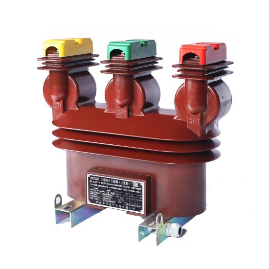
The LSZY-10 is a high-reliability, cast-resin insulated current transformer (CT) engineered for precise current measurement and robust protective relaying in medium-voltage power systems operating at a nominal system voltage of 10 kV, with an IEC-rated insulation level of 11 kV. Designed in strict compliance with IEC 61869-2 and GB/T 20840.2, this device leverages advanced vacuum pressure impregnation (VPI) epoxy resin technology to deliver exceptional dielectric strength, environmental resilience, and long-term operational stability. Unlike traditional oil-immersed CTs, the LSZY-10 eliminates fire hazards, oil leakage risks, and maintenance-intensive fluid management, making it ideal for both indoor substations and outdoor switchyards.
Operating Principle of Cast-Resin Insulation
Cast-resin insulation in the LSZY-10 is achieved through a multi-stage VPI process where high-purity epoxy resin is vacuum-degassed, then pressure-injected around the primary conductor and secondary windings. This ensures complete void-free encapsulation of the magnetic core—typically constructed from grain-oriented electrical steel (GOES)—and all internal components. The resulting monolithic structure provides uniform electric field distribution, superior partial discharge resistance (<5 pC at 1.2 × Um/√3), and excellent thermal conductivity (0.2–0.3 W/m·K). The resin matrix also offers mechanical rigidity, protecting windings from vibration-induced fatigue during short-circuit events. Crucially, the absence of air pockets or moisture ingress pathways enhances long-term dielectric integrity under thermal cycling and pollution exposure, critical for installations in coastal or industrial environments.
Advantages Over Oil-Immersed Designs
Compared to oil-filled CTs, the LSZY-10’s dry-type construction delivers significant operational and safety benefits. It is inherently non-flammable, eliminating fire propagation risks in confined spaces such as urban substations or underground vaults. There is no need for oil sampling, degassing, or leak monitoring, reducing lifecycle maintenance costs by up to 40%. The compact footprint—enabled by higher dielectric strength of epoxy versus oil—allows for denser switchgear layouts. Additionally, the LSZY-10 exhibits faster thermal response due to direct heat conduction through solid resin, improving accuracy during transient overloads. Environmental compliance is enhanced, as the unit contains no hazardous substances regulated under RoHS or REACH, simplifying end-of-life disposal.
Typical Applications Overview
The LSZY-10 is deployed across diverse infrastructure sectors requiring accurate current sensing and dependable fault detection. In utility-owned 10 kV distribution networks, it interfaces with revenue-class kWh meters and digital protective relays (e.g., SEL-751, Siemens 7SJ62). Industrial facilities use it for motor protection, load profiling, and harmonic monitoring in 11 kV plant distribution systems. Renewable energy projects—particularly solar farms with 10 kV collector grids—rely on its stable ratio error performance under variable loading conditions. Its IP54-rated terminal box ensures reliable operation in dusty or humid environments, while UV-stabilized resin permits direct outdoor mounting without weather shields.
Technical Specifications
The LSZY-10 is engineered to meet stringent electrical and environmental performance criteria defined by international and Chinese national standards. Below is a comprehensive specification table followed by detailed service condition parameters.
| Parameter | Value |
|---|---|
| Rated System Voltage (IEC) | 11 kV |
| Domestic System Voltage | 10 kV |
| Primary Current Rating | 50 A to 3000 A (standard); up to 4000 A (custom) |
| Secondary Current | 1 A or 5 A |
| Current Ratio(s) | Single or dual ratio (e.g., 600/1 A + 600/5 A) |
| Accuracy Class (Metering) | 0.2S, 0.5S per IEC 61869-2 |
| Accuracy Class (Protection) | 5P10, 5P20, 10P10, 10P20 |
| Rated Burden (VA) | 2.5 VA to 30 VA (user-selectable per winding) |
| Insulation Level (Um / Up) | 12 kV / 75 kV (1 min AC withstand) |
| Lightning Impulse Withstand | 95 kV (peak, 1.2/50 μs) |
| Short-Time Thermal Current | 20 × Ipn for 1 s (e.g., 60 kA for 3000 A primary) |
| Dynamic Withstand Current | 2.5 × thermal current (e.g., 150 kA peak) |
| Ambient Temperature Range | −40°C to +40°C |
| Altitude Limit | ≤ 1000 m (derating required above) |
| Relative Humidity | Up to 95% non-condensing |
| Core Material | Grain-Oriented Electrical Steel (GOES), M4 grade |
| Insulation System | VPI Epoxy Resin, UL 94 V-0 rated |
Standard Service Conditions
The LSZY-10 is rated for continuous operation under IEC 60060-1 standard atmospheric conditions: ambient temperature between −40°C and +40°C, relative humidity not exceeding 95% (non-condensing), and installation altitude ≤1000 m above sea level. At altitudes above 1000 m, the dielectric withstand voltage must be derated by 1% per 100 m increment. For example, at 2000 m, the 1-minute AC test voltage reduces from 75 kV to 67.5 kV. The unit is designed for three-phase systems with balanced or unbalanced loading and can tolerate harmonic distortion up to THDI = 15% without exceeding accuracy class limits. Installation orientation is vertical or horizontal, with primary conductor centered within the core aperture to minimize phase-shift errors.
Electrical Performance Tolerances
Per IEC 61869-2, the LSZY-10 maintains strict error tolerances under defined operating conditions. For a 0.2S class metering winding at 100% rated current and rated burden, current error must not exceed ±0.2%, and phase displacement ≤ ±10 minutes. At 20% load, error tolerance widens to ±0.35%. Protection windings (e.g., 5P20) guarantee composite error ≤5% when subjected to 20× rated current into specified burden. Ratio error is factory-calibrated to ±0.1% using precision bridge methods traceable to NIM (National Institute of Metrology, China). Saturation flux density of the GOES core is maintained below 1.7 T under maximum continuous load to prevent remanence-induced inaccuracies after fault clearance.
Typical Applications
The LSZY-10 serves as a foundational component in modern medium-voltage infrastructure, enabling accurate energy accounting and rapid fault isolation across multiple sectors.
Substation Secondary Metering
In 10 kV/11 kV utility substations, the LSZY-10 interfaces directly with Class 0.2S revenue meters for billing-grade energy measurement. Its low phase-shift error (<5 minutes at 100% In) ensures minimal reactive power measurement deviation, critical for power factor correction schemes. Dual-ratio configurations allow simultaneous connection to both tariff meters and SCADA RTUs—e.g., a 1200/1 A winding feeds the kWh meter, while a 1200/5 A winding supplies analog inputs to the substation automation system. The CT’s high saturation point prevents waveform clipping during motor-start inrush currents, preserving data integrity for load forecasting algorithms.
Industrial Power Distribution
Within manufacturing plants operating 11 kV internal grids, the LSZY-10 protects critical assets such as induction furnaces, large compressors, and rectifier transformers. Protection-class windings (e.g., 10P20) feed differential or overcurrent relays that trip circuit breakers within 30 ms of fault inception. The cast-resin body resists chemical vapors common in petrochemical or pulp-and-paper facilities, unlike oil-filled units prone to gasket degradation. In arc-furnace applications, the CT withstands severe electromagnetic interference due to its fully shielded secondary terminals and grounded resin housing.
Renewable Energy Integration
Solar photovoltaic (PV) farms with 10 kV collector systems deploy the LSZY-10 for both generation metering and anti-islanding protection. During cloud transients, rapid irradiance changes cause current fluctuations; the LSZY-10’s linear response down to 1% of rated current ensures accurate yield reporting. Its immunity to DC offset—critical when inverters inject asymmetric currents—is verified via type tests per IEC 61869-2 Annex D. In wind turbine step-up transformers, the CT monitors grid-synchronization currents, with 5P10 windings triggering disconnection if islanding is detected per IEEE 1547 requirements.
Rural and Suburban Distribution Networks
For overhead or underground 10 kV feeders serving residential zones, the LSZY-10 enables automated fault location via traveling-wave detection systems. Its consistent turns ratio across temperature extremes (−30°C to +50°C) ensures reliable impedance-based fault distance calculation. Mounted on pole-top reclosers or pad-mounted switchgear, the unit’s UV-resistant resin housing withstands decades of solar exposure without embrittlement. In smart grid deployments, secondary outputs connect to IoT-enabled sensors that stream real-time load data to distribution management systems (DMS) for dynamic voltage regulation.
Compliance with International Standards
The LSZY-10 is certified to both global and Chinese national standards, ensuring interoperability and regulatory acceptance across markets.
IEC 61869-2 Compliance Details
As a dedicated current transformer, the LSZY-10 adheres fully to IEC 61869-2:2012 (“Instrument transformers – Part 2: Additional requirements for current transformers”). This includes mandatory type tests for temperature rise (≤60 K for resin, ≤50 K for windings), short-circuit withstand (250×In²t), and partial discharge (≤10 pC at 1.2×Um/√3). Accuracy verification follows Clause 6.3, with error measurements conducted at 5%, 20%, 100%, and 120% of rated current. The standard mandates separate designation of metering (e.g., 0.2S) and protection (e.g., 5P20) windings, which the LSZY-10 implements via physically isolated secondary coils wound on distinct core limbs to prevent mutual interference.
GB/T 20840.2 Alignment
The Chinese national standard GB/T 20840.2-2013 mirrors IEC 61869-2 but adds localized requirements. Notably, it specifies stricter lightning impulse levels for 10 kV systems (95 kV vs. IEC’s 75 kV basic insulation level) and mandates salt fog testing (ASTM B117) for coastal installations. The LSZY-10 exceeds these by incorporating hydrophobic resin additives that reduce surface conductivity under pollution. GB/T also requires mechanical load testing of primary terminals (1000 N static force), which the LSZY-10 passes via reinforced copper-alloy bushings. Certification is issued by CEPREI or SGS China after witnessed factory acceptance tests (FAT).
Key Differences Between IEC and Domestic Standards
While IEC 61869-2 focuses on functional performance, GB/T 20840.2 emphasizes environmental durability for China’s diverse climate zones. For instance, GB/T requires −45°C cold-impact testing of resin housings, whereas IEC only specifies −25°C. Harmonic immunity testing under GB/T includes injection of 3rd, 5th, and 7th harmonics up to 20% amplitude—more stringent than IEC’s generic THD limits. However, both standards converge on core accuracy definitions: 0.2S class demands error ≤±0.2% at 100% In, ensuring global meter compatibility.
On-Site Testing Procedures
Post-installation verification ensures the LSZY-10 performs within specification before energization.
Insulation Resistance Test
Using a 2500 V DC megohmmeter, measure insulation resistance between primary-to-secondary, primary-to-ground, and secondary-to-ground. Acceptance criterion: ≥1000 MΩ at 25°C. Values below 500 MΩ indicate moisture ingress or resin cracking. Temperature correction is applied per IEEE 43: Rcorr = Rmeas × 2(40−T)/10. For example, a 600 MΩ reading at 15°C corrects to 2400 MΩ—well above threshold.
Turns Ratio Test
Apply low-voltage AC (5–10 V) to the secondary winding and measure induced primary voltage. Calculate actual ratio as Vsec/Vprim. Tolerance: ±0.2% for metering classes, ±0.5% for protection. Modern ratio testers (e.g., Omicron CT Analyzer) automate this with <0.05% uncertainty. Deviations >1% suggest inter-turn shorts or incorrect tap selection.
Polarity Test
Verify reducing polarity using a 1.5 V battery and DC milliammeter. Momentarily connect (+) to P1 and (−) to P2; a positive kick on the meter connected to S1(+)–S2(−) confirms correct polarity. Incorrect polarity causes watt-hour meters to register reverse energy flow—a critical error in net-metering PV systems.
Power Frequency Withstand Voltage Test
Apply 28 kV RMS (40% of 75 kV rating) at 50 Hz for 1 minute between primary and grounded secondary/housing. No flashover or excessive leakage current (>1 mA) is permitted. This reduced test validates insulation integrity without overstressing aged resin. Full 75 kV tests are reserved for factory certification.
Short-Circuit Test (for CT)
Inject 10–20× rated secondary current (e.g., 50 A into 5 A winding) and verify relay operation or burden voltage drop. For 5P20 windings, secondary voltage must remain linear up to 100 V (20×5 A × 1 Ω burden). Nonlinearity indicates core saturation, compromising protection coordination.
Preventive Maintenance Guide
Although cast-resin CTs require minimal upkeep, scheduled inspections extend service life beyond 30 years.
Periodic Inspection Protocol
Annual visual checks include: (1) Cracking or tracking on resin surface (use UV lamp for early detection), (2) Corrosion on terminal bolts (torque to 15 N·m if loose), (3) Moisture in terminal box (replace desiccant if silica gel turns pink). Infrared thermography should show <10°C differential between phases under load—hotspots indicate poor contact or internal faults. Secondary circuit continuity is verified with <0.1 Ω resistance.
Maintenance Intervals and Fault Diagnosis
Every 5 years, perform insulation resistance and ratio tests as baseline comparisons. Common failure modes include: (1) Secondary open-circuit during operation—causes dangerous overvoltage (>2 kV) and core remanence; always short terminals before disconnecting meters. (2) Partial discharge erosion—detected via ultrasonic sensors emitting >20 dBμV signals. (3) Thermal aging—resin discoloration (amber to brown) correlates with >130°C cumulative exposure. Replace if tan δ exceeds 0.02 at 10 kV.
| Interval | Action |
|---|---|
| Annually | Visual inspection, IR scan, terminal torque check |
| Every 5 Years | Insulation resistance, turns ratio, polarity verification |
| After Major Fault | Full suite of on-site tests + core remanence check |
| Every 10 Years | Partial discharge measurement (if available) |
Conclusion
The LSZY-10 11kV cast-resin current transformer represents a benchmark in medium-voltage instrumentation, combining IEC 61869-2 and GB/T 20840.2 compliance with robust engineering for demanding utility and industrial environments. Its VPI epoxy resin encapsulation eliminates the fire and environmental liabilities of oil-filled alternatives while delivering superior dielectric performance—evidenced by 75 kV AC withstand strength and <5 pC partial discharge levels. The use of GOES magnetic cores ensures metrological stability across wide current ranges, supporting both 0.2S revenue metering and 10P20 protection functions within a single compact unit. Field-proven reliability stems from rigorous type testing, including 250×In²t short-circuit endurance and −40°C thermal shock resistance. With a design life exceeding 30 years under standard service conditions, the LSZY-10 minimizes total cost of ownership through zero fluid maintenance, resistance to pollution and UV degradation, and compatibility with modern digital substation architectures. Its adherence to dual international and Chinese standards facilitates seamless deployment across global markets, from smart city distribution networks to remote renewable energy sites. For engineers specifying instrumentation for 10 kV/11 kV systems, the LSZY-10 provides a technically uncompromised solution that balances precision, safety, and longevity.