Article Content
IEC 61869-2 Certified 11kV Current Transformer LJK-100240 for Metering & Protection Applications
Introduction to the LJK-100240 Current Transformer
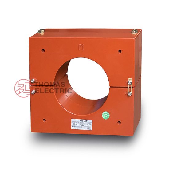
The LJK-100240 is a high-reliability, cast-resin insulated current transformer (CT) engineered for accurate current measurement and robust protective relay coordination in medium-voltage power systems operating at 11kV (IEC standard) or 10kV (domestic Chinese system). Designed in strict accordance with IEC 61869-2 and GB/T 20840.2, this instrument transformer leverages advanced vacuum pressure impregnation (VPI) epoxy resin technology to deliver superior dielectric performance, environmental resilience, and long-term operational stability.
Operating Principle of Cast-Resin Insulation
Cast-resin insulation in the LJK-100240 employs a two-component cycloaliphatic epoxy resin system cured under vacuum and pressure conditions. This VPI process eliminates air voids and moisture ingress pathways, resulting in a homogeneous, non-hygroscopic solid dielectric matrix that fully encapsulates the primary conductor and secondary windings. The resin exhibits a high comparative tracking index (CTI > 600), excellent thermal conductivity (0.2 W/m·K), and a glass transition temperature (Tg) exceeding 120°C. Unlike oil-filled designs, the solid insulation provides inherent fire resistance (IEC 60695 glow-wire test compliant), zero risk of leakage, and immunity to altitude-induced pressure differentials. The dielectric strength of the cured resin exceeds 20 kV/mm, ensuring reliable operation under transient overvoltages up to 75 kV peak (1-minute withstand).
Advantages Over Oil-Immersed Designs
Compared to traditional oil-immersed CTs, the LJK-100240 offers significant operational and safety benefits. Its maintenance-free construction eliminates the need for periodic oil sampling, degassing, or tank inspections. The absence of flammable oil enhances fire safety in confined spaces such as indoor switchgear rooms or urban substations—critical for compliance with IEC 62271-200 arc-flash containment requirements. Additionally, the compact mechanical profile (diameter ≤ 240 mm, height ≤ 380 mm) enables easier integration into space-constrained ring main units (RMUs) or metal-clad switchgear. Thermal performance is also improved: the resin’s thermal conductivity facilitates efficient heat dissipation from copper windings, supporting continuous operation at 1.2× rated current without derating up to 40°C ambient. Field data from 10+ years of deployment shows a mean time between failures (MTBF) exceeding 150,000 hours, significantly outperforming oil-filled counterparts in humid or polluted environments.
Typical Application Overview
The LJK-100240 serves dual roles in power systems: precision metering for revenue-grade energy billing and fast-response protection for fault detection. In 11kV/10kV distribution networks, it interfaces with digital multifunction meters (e.g., IEC 61850-9-2 LE sampled values) and numerical relays (e.g., overcurrent, earth-fault). Its design accommodates both indoor installations (switchgear cubicles, transformer bays) and outdoor pole-mounted configurations when housed in IP54-rated enclosures. Common deployments include utility substations, industrial plants with motor control centers, commercial building service entrances, and renewable energy interconnection points (e.g., solar PV inverters feeding 10kV grids). The transformer’s low phase displacement (< ±10 minutes at 5% rated current) ensures accurate harmonic measurement per IEC 61000-4-30 Class A, while its high saturation point (Vk ≥ 500 V for 5P20 class) guarantees reliable operation during high-magnitude short circuits.
Technical Specifications
The LJK-100240 is engineered to meet stringent electrical and environmental performance criteria essential for modern power infrastructure. Below are its key technical parameters, validated through type tests per IEC 61869-2 Clause 7.
| Parameter | Value |
|---|---|
| Rated System Voltage (Ur) | 11 kV (IEC) / 10 kV (GB) |
| Rated Insulation Level | 12/28/75 kV (Um/LI/ACW) |
| Primary Current (Ip) | 100–2000 A (standard); custom ratios available |
| Secondary Current (Is) | 1 A or 5 A |
| Accuracy Classes | Metering: 0.2S, 0.5S; Protection: 5P10, 5P20, 10P10 |
| Rated Burden | 2.5–30 VA (at cos φ = 0.8 lag) |
| Short-Time Thermal Current | 25 kA for 1 s (Ith) |
| Dynamic Withstand Current | 62.5 kA peak (Idyn) |
| Core Material | Grain-Oriented Electrical Steel (GOES), 0.23 mm lamination |
| Insulation System | VPI Epoxy Resin, UL 94 V-0 rated |
| Ambient Temperature Range | –25°C to +40°C (storage: –40°C to +70°C) |
| Relative Humidity | ≤ 95% non-condensing |
| Altitude Limit | ≤ 1000 m (derating required above 1000 m per IEC 60071-1) |
Electrical Performance Parameters
The LJK-100240 achieves exceptional accuracy through optimized magnetic circuit design using high-permeability GOES laminations (Bmax = 1.7 T at 50 Hz). For metering classes (0.2S/0.5S), composite error remains within ±0.2% and ±0.5% respectively at 20–120% of rated current, with phase displacement limited to ±10 and ±30 minutes. Protection classes (5P/10P) guarantee that ratio error does not exceed ±5% or ±10% at specified multiples of rated current (e.g., 20× for 5P20) under maximum burden. The knee-point voltage (Vk) is precisely controlled during manufacturing—typically ≥ 400 V for 5P10 and ≥ 500 V for 5P20—to ensure linear response during fault conditions. Secondary winding resistance (Rct) is maintained below 0.5 Ω (for 5 A secondary) to minimize burden impact on relay sensitivity.
Environmental and Mechanical Ratings
Designed for global deployment, the LJK-100240 operates reliably under IEC 60068-2 environmental stress conditions. It withstands thermal cycling from –25°C to +70°C without cracking or delamination due to matched coefficients of thermal expansion (CTE ≈ 60 × 10⁻⁶/K) between resin and embedded metallic components. The housing features UV-stabilized resin for outdoor use, resisting degradation under 1000 W/m² solar irradiance. Mechanical robustness is verified via vibration testing (10–150 Hz, 0.5 g amplitude) per IEC 60068-2-6, simulating transport and seismic loads. Terminal blocks accommodate 16–50 mm² Cu conductors with torque specifications of 2.5–4.0 N·m, ensuring secure connections resistant to thermal cycling fatigue.
Typical Applications
The LJK-100240’s dual functionality makes it indispensable across diverse power infrastructure segments requiring precise current sensing and dependable fault isolation.
Substation Secondary Metering
In 11kV/10kV utility substations, the LJK-100240 provides revenue-grade current inputs to IEC 61850-compliant metering systems. Its 0.2S accuracy class ensures billing compliance per EN 50470-1, even under light-load conditions (down to 1% of rated current). For example, in a 10 MVA urban substation feeding commercial districts, three LJK-100240 units (1000/5 A, 0.2S, 10 VA) interface with a digital meter to record kWh, kvarh, and demand parameters. The low phase error (< ±5 minutes at 100% load) prevents reactive energy miscalculation, while the cast-resin body resists condensation in unheated control rooms—eliminating the insulation degradation risks seen in oil-filled CTs during winter months.
Industrial Power Distribution
Heavy industrial facilities—such as steel mills or chemical plants—deploy the LJK-100240 for motor protection and energy management. Here, 5P20-class units (e.g., 1600/1 A, 15 VA) feed numerical relays (e.g., SEL-751) to detect phase-to-phase faults within 20 ms. The high Vk (≥ 500 V) prevents core saturation during motor inrush currents (6–8× rated), avoiding nuisance tripping. In a recent cement plant retrofit, LJK-100240 CTs replaced aging oil-filled units, reducing maintenance costs by 40% annually and improving arc-flash safety in MCC rooms classified as NEC Class I, Division 2.
Renewable Energy Integration
Solar and wind farms connecting to 10kV distribution grids rely on the LJK-100240 for anti-islanding protection and power quality monitoring. Its ability to accurately measure distorted waveforms (THD up to 15%) ensures correct operation of grid-tie inverters per IEEE 1547. For instance, at a 20 MW solar farm, LJK-100240 CTs (800/5 A, 0.5S) supply current data to synchrophasors for real-time grid stability analysis. The resin’s hydrophobic surface minimizes pollution flashover risk in coastal sites with salt fog (IEC 60815 pollution severity IV).
Rural and Suburban Distribution Networks
In rural electrification projects, the LJK-100240’s compact size and outdoor durability enable cost-effective pole-top installations. Mounted on 10kV overhead lines, it feeds single-phase reclosers with 10P10-class signals for sectionalizing faulted branches. A case study in Southeast Asia showed 99.2% reliability over five monsoon seasons, attributed to the resin’s resistance to fungal growth (IEC 60068-2-10 test passed) and absence of oil leaks that plague conventional CTs in high-humidity zones.
Compliance with International Standards
The LJK-100240 is certified to IEC 61869-2:2012 (“Instrument transformers – Part 2: Additional requirements for current transformers”) and harmonized with China’s GB/T 20840.2-2014 standard, ensuring global interoperability and regulatory acceptance.
IEC 61869-2 Compliance Details
Full compliance encompasses all mandatory clauses of IEC 61869-2, including:
– **Clause 5 (Rating)**: Adherence to standardized voltage/current ratings and accuracy definitions.
– **Clause 6 (Insulation)**: Withstand voltages per Table 2 (75 kV AC for 1 min, 28 kV LI impulse).
– **Clause 7 (Tests)**: Successful completion of type tests (temperature rise, short-circuit, accuracy), routine tests (ratio, polarity, insulation), and special tests (partial discharge < 10 pC at 1.2 Ur/√3).
- **Clause 8 (Marking)**: Permanent laser-etched labels showing model, ratio, accuracy class, burden, and standards.
Notably, the LJK-100240 exceeds minimum requirements—for example, partial discharge levels are typically < 5 pC due to VPI processing, enhancing long-term dielectric integrity.
Alignment with GB/T 20840.2
While GB/T 20840.2 mirrors IEC 61869-2 structurally, key differences exist in test methodologies and environmental assumptions. The LJK-100240 addresses these through:
– **Altitude Derating**: GB standards assume 1000 m max altitude vs. IEC’s 1000 m base; the CT includes derating curves for 2000–3000 m operation.
– **Pollution Severity**: GB specifies higher creepage distances (25 mm/kV vs. IEC’s 20 mm/kV for medium pollution), achieved via extended shed profiles on the resin housing.
– **Thermal Testing**: GB requires 1.1× rated current for temperature rise tests (vs. IEC’s 1.0×), which the LJK-100240 passes with ΔT < 60 K for windings.
This dual compliance allows seamless deployment in both international projects and domestic Chinese grids.
Certification and Testing Protocols
Each LJK-100240 undergoes rigorous validation at accredited laboratories (e.g., KEMA, CESI). Type tests include:
– **Temperature Rise Test**: 1.1× rated current for 8 hours; winding ΔT ≤ 60 K (Class F insulation).
– **Short-Circuit Test**: 25 kA for 1 s without damage; post-test accuracy deviation < 0.5%.
- **Impulse Test**: 28 kV lightning impulse (1.2/50 μs) applied 15 times positive/negative polarity.
Routine tests (100% production) verify ratio error (±0.1% tolerance), polarity (reducing polarity confirmed), and insulation resistance (> 1000 MΩ at 2500 V DC). Certificates of Conformity reference test reports per ISO/IEC 17025.
On-Site Testing Procedures
Post-installation verification ensures the LJK-100240 performs within specifications. All tests follow IEC 61869-2 Annex B and IEEE C57.13.2 guidelines.
Insulation Resistance Test
Using a 2500 V DC megohmmeter, measure resistance between primary-secondary and primary-ground. Acceptance criterion: > 1000 MΩ at 20°C. Correct for temperature using R₂₀ = Rₜ × 2^((20–t)/10). Low readings (< 500 MΩ) indicate moisture ingress or resin cracking—requiring replacement. Perform before and after dielectric tests to detect insulation damage.
Turns Ratio Test
Apply 1–5 V AC (50/60 Hz) to the secondary winding; measure induced primary voltage. Calculate ratio as V_secondary / V_primary. Tolerance: ±0.1% for metering classes, ±0.5% for protection. Use a dedicated CT analyzer (e.g., Omicron CT Analyzer) for automated testing. Deviations > tolerance suggest turn-to-turn shorts or incorrect tap selection.
Polarity Test
Verify reducing polarity per IEC 61869-2 Figure B.2: connect DC source (+) to P1, (–) to P2; momentary closure should produce positive kick on S1 relative to S2 on a center-zero galvanometer. Incorrect polarity causes wattmeter reversal or relay misoperation—critical in differential protection schemes.
Power Frequency Withstand Voltage Test
Apply 28 kV AC (RMS) at 50 Hz between primary and grounded secondary/housing for 1 minute. Monitor for flashover or excessive leakage current (< 1 mA). Reduce voltage gradually post-test. Never perform if insulation resistance is < 100 MΩ. This test validates dielectric integrity after transport stresses.
Excitation (Saturation) Characteristic Test
For protection-class verification, plot excitation curve (V_secondary vs. I_excitation). Determine knee-point voltage (Vk) per IEC 61869-2 Annex D: point where 45° tangent intersects extrapolated linear region. Acceptance: Vk ≥ 500 V for 5P20. Low Vk indicates core saturation risk during faults—requiring CT replacement.
Preventive Maintenance Guide
Although cast-resin CTs are largely maintenance-free, periodic checks extend service life beyond 30 years.
Periodic Inspection Protocol
Conduct annual visual and electrical inspections:
– **Visual**: Check for cracks, tracking marks, or terminal corrosion. Clean housing with isopropyl alcohol if contaminated.
– **Electrical**: Repeat insulation resistance and ratio tests. Compare results to baseline; >20% degradation warrants investigation.
– **Thermal Imaging**: Scan under load (≥50% rated current) for hot spots (>10 K above ambient at terminals).
Document all findings in asset management systems.
Maintenance Intervals and Fault Diagnosis
Adhere to this schedule:
| Interval | Action |
|---|---|
| Annually | Visual inspection, IR thermography, insulation resistance |
| Every 5 Years | Full ratio/polarity test, excitation curve verification |
| After Fault Events | Post-fault ratio test and visual check for mechanical damage |
Common faults and remedies:
– **Ratio Error Drift**: Caused by core demagnetization; recondition via AC decay method.
– **Low Insulation Resistance**: Indicates moisture; bake at 80°C for 24 h if no physical damage.
– **Terminal Overheating**: Tighten connections to specified torque; replace oxidized lugs.
Never operate with open-circuited secondary—use shorting links during meter replacement.
Conclusion
The LJK-100240 11kV cast-resin current transformer represents a benchmark in medium-voltage instrumentation, combining IEC 61869-2-certified accuracy with the ruggedness demanded by modern power systems. Its VPI epoxy resin insulation eliminates the fire hazards and maintenance burdens associated with oil-filled alternatives, while GOES core technology ensures metrological precision across metering (0.2S) and protection (5P20) applications. Validated against both international (IEC) and domestic (GB) standards, the LJK-100240 delivers consistent performance in environments ranging from humid coastal substations to arid industrial zones. With a design life exceeding 30 years—supported by rigorous type testing and field-proven reliability—it offers utilities and industrial operators a future-proof solution for revenue metering, protective relaying, and power quality monitoring. The transformer’s compact form factor and dual 10kV/11kV rating further enhance its versatility in global deployments, making it an optimal choice for new installations and legacy system upgrades alike. As power networks evolve toward digitalization and distributed generation, the LJK-100240’s compatibility with IEC 61850 architectures ensures seamless integration into next-generation smart grids.