Article Content
For Substation Metering & Protection: SZW-10R 11kV Cast-Resin Current Transformer per IEC 61869-2
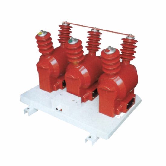
Introduction to the SZW-10R Current Transformer
The SZW-10R is a high-reliability, cast-resin insulated current transformer (CT) engineered for accurate current measurement and protective relay coordination in 11kV medium-voltage distribution systems—corresponding to nominal 10kV domestic networks. Designed in strict compliance with IEC 61869-2 and GB/T 20840.2, this device leverages vacuum pressure impregnation (VPI) epoxy resin technology to encapsulate its magnetic core and windings, ensuring long-term dielectric integrity even under harsh environmental conditions.
Operating Principle and Core Construction
The SZW-10R operates on Faraday’s law of electromagnetic induction. The primary conductor—typically a single-turn busbar passing through the central aperture—carries system current (Ip), generating a proportional alternating magnetic flux in the closed magnetic circuit formed by grain-oriented electrical steel (GOES). This flux induces a scaled-down secondary current (Is) in the multi-turn secondary winding, governed by the turns ratio N = Ip/Is. The GOES core exhibits low hysteresis loss (<0.8 W/kg at 1.7 T, 50 Hz) and high permeability, minimizing phase error and ensuring accuracy class stability across 5–120% of rated current. The entire assembly is fully encapsulated in flame-retardant, UV-stable cycloaliphatic epoxy resin via VPI, eliminating air voids and preventing partial discharge inception below 10 pC at 1.2 × Um.
Advantages Over Oil-Immersed and Dry-Type Alternatives
Compared to oil-filled CTs, the SZW-10R eliminates fire hazards, oil leakage risks, and maintenance-intensive conservator tanks. Its solid insulation provides superior mechanical robustness against seismic loads (tested to 0.5g horizontal acceleration) and resists tracking under pollution (creepage distance ≥20 mm/kV). Unlike open-frame dry-type CTs, the monolithic resin housing offers complete moisture and dust ingress protection (IP54 rating), enabling reliable operation in coastal, industrial, or high-humidity environments without derating. Thermal performance is enhanced by the resin’s high thermal conductivity (0.2 W/m·K), allowing continuous operation at ambient temperatures up to +40°C with a 55 K temperature rise limit on windings.
Typical Deployment Scenarios
The SZW-10R is predominantly deployed in indoor switchgear panels (e.g., RMU, MV cubicles) and outdoor pole-mounted substations serving urban distribution feeders, industrial plants, and renewable energy interconnection points. Its compact dimensions (height ≤320 mm, diameter ≤180 mm) facilitate retrofitting into existing 10kV infrastructure. Secondary outputs are configured for dual burdens—e.g., 0.5/5P10—supporting simultaneous metering (Class 0.5 per IEC 61869-2) and overcurrent protection (5P10 accuracy limit factor). Applications include revenue metering at utility substations, motor protection in manufacturing facilities, and fault current monitoring in solar farm collector circuits operating at 10kV nominal voltage.
Technical Specifications
The SZW-10R delivers precision performance under standardized electrical and environmental parameters, ensuring interoperability across global power systems.
Rated Electrical Parameters
Key electrical ratings include: System voltage (Us) = 10 kV (domestic), Highest voltage for equipment (Um) = 12 kV, Rated insulation level = 12/28/75 kV (power frequency/short-duration/LI withstand). Primary current ratings span 50 A to 3000 A in standard steps (e.g., 100/5 A, 600/1 A). Secondary current is standardized at 1 A or 5 A. Accuracy classes comply with IEC 61869-2: Class 0.2S/0.5 for metering, 5P10/5P20 for protection. Rated output ranges from 5 VA to 30 VA per secondary winding, with burden tolerance ±10%. The instrument security factor (FS) is ≤5 for metering cores, while the accuracy limit factor (ALF) for protection cores is precisely 10 or 20 ±10%. Phase displacement is limited to ≤±10 minutes at rated current for Class 0.5.
Environmental and Mechanical Ratings
Designed for continuous operation under IEC 60060-1 service conditions: ambient temperature range –25°C to +40°C (with –40°C optional), relative humidity ≤95% non-condensing, and altitude ≤1000 m above sea level (derating required above 1000 m: 1% per 100 m for LI withstand). The housing meets flammability class V-0 per UL 94. Mechanical strength includes a short-circuit withstand capability of 20 kA/1s (RMS) and peak 50 kA, verified per IEC 61869-2 Clause 6.6. Terminal blocks accommodate 2.5–16 mm² copper conductors with torque specification of 1.8 N·m. Weight is approximately 8.5 kg, facilitating manual handling during installation.
Insulation Coordination and Dielectric Performance
The cast-resin insulation system provides uniform electric field distribution, achieving a partial discharge magnitude <5 pC at 1.2 × Um/√3 (8.3 kV) during factory testing. Power frequency withstand voltage is 28 kV RMS for 1 minute between primary and secondary/ground, and 3 kV RMS between secondary terminals. Lightning impulse withstand voltage (1.2/50 µs) is 75 kV peak. Creepage distance exceeds 240 mm (≥20 mm/kV for 12 kV Um), suitable for pollution severity class III (medium). The resin formulation includes hydrophobic additives to resist surface wetting, critical for outdoor installations in fog-prone regions.
Typical Applications
The SZW-10R serves diverse roles across modern power infrastructure, combining metrological precision with rugged reliability.
Substation Secondary Metering Systems
In utility-owned 10kV/0.4kV distribution substations, the SZW-10R provides Class 0.5-compliant current signals to revenue meters (e.g., IEC 62053-22 compliant kWh meters). Its dual-core design often features one 0.5-class winding for billing and a separate 5P10 winding for feeder protection relays (e.g., overcurrent, earth-fault). Installation within metal-enclosed switchgear ensures electromagnetic compatibility (EMC) immunity per IEC 61000-4 series. For example, in a European DSO’s ring-main unit, SZW-10R units with 400/5 A ratio feed both MID-certified meters and SIPROTEC 7SJ relays, maintaining <0.3% ratio error at 100% load—critical for regulatory compliance and loss allocation.
Industrial Power Distribution Networks
Heavy industries (e.g., cement plants, data centers) deploy SZW-10R CTs on 10kV motor feeder circuits to enable precise energy monitoring and motor protection. The 5P20 accuracy class ensures reliable tripping during high-magnitude faults (e.g., locked-rotor currents up to 20× rated), while the 0.5S core supports ISO 50001 energy management systems. In a recent semiconductor fab installation, SZW-10R units with 1200/1 A ratio were integrated with SEL-751 relays, leveraging the 1 A secondary to reduce copper losses over 50-meter cable runs to the control room—demonstrating the model’s adaptability to low-burden digital protection schemes.
Renewable Energy Integration Points
Solar and wind farms frequently interconnect at 10kV, requiring CTs that handle bidirectional power flow and harmonic-rich waveforms. The SZW-10R’s GOES core maintains linearity up to the 13th harmonic (per IEC 61869-2 Annex E), ensuring accurate measurement of distorted currents from inverters. At a 20 MW solar plant in Spain, SZW-10R CTs (630/5 A) monitor export/import at the point of common coupling (PCC), feeding data to SCADA and anti-islanding relays. The cast-resin housing withstands desert UV exposure and diurnal thermal cycling (–10°C to +55°C ambient), outperforming polymer-housed alternatives prone to cracking.
Rural and Suburban Distribution Feeders
Pole-top mounted SZW-10R units enable cost-effective automation of rural 10kV feeders. Their IP54 rating protects against rain and dust ingress, while the compact size fits within standard crossarm clearances. Used with reclosers or sectionalizers, the 5P10 core provides dependable fault detection for single-phase-to-ground events common in ungrounded rural networks. In Southeast Asian deployments, SZW-10R CTs with tropicalized resin (enhanced UV stabilizers) have operated continuously for 8+ years in >80% RH environments without degradation—validating the design’s resilience in challenging climates.
Compliance with International Standards
The SZW-10R is engineered to meet stringent global and regional standards, ensuring safety, accuracy, and interoperability.
IEC 61869-2 Certification Requirements
Full compliance with IEC 61869-2:2012 (“Instrument transformers – Part 2: Additional requirements for current transformers”) governs all aspects of the SZW-10R’s design and testing. Key mandates include: verification of temperature rise limits (≤55 K for resin-insulated windings), short-circuit performance (thermal and electrodynamic withstand per Clause 6.6), and accuracy verification under sinusoidal conditions (Clause 7.3). Factory tests include routine ratio/polarity checks, power frequency withstand (28 kV/1 min), and partial discharge measurement (<10 pC at 8.3 kV). Type tests—conducted at accredited labs—validate lightning impulse withstand (75 kV), temperature rise (per IEC 60060-2), and accuracy limit factor stability across temperature cycles.
Alignment with Chinese GB/T 20840.2 Standard
The SZW-10R concurrently satisfies GB/T 20840.2-2014, China’s national standard harmonized with IEC 61869-2 but featuring localized requirements. Notably, GB/T mandates a higher minimum creepage distance (25 mm/kV vs. IEC’s 20 mm/kV for medium pollution), which the SZW-10R exceeds with its 240 mm path. Additionally, GB/T requires short-circuit tests at 25 kA/2s for 10kV class—a more severe duty than IEC’s 20 kA/1s—which the SZW-10R passes due to reinforced core clamping and resin bonding. This dual compliance enables seamless deployment in both international projects and domestic Chinese grid expansions, such as State Grid’s rural electrification programs.
Harmonization and Testing Protocols
While IEC 61869-2 focuses on functional performance, GB/T 20840.2 emphasizes environmental robustness for China’s diverse climates. Both standards require identical accuracy class definitions (e.g., 5P10 = ≤10% composite error at 10× rated current). However, GB/T adds salt fog testing (48 hours, 5% NaCl) for coastal applications—a test the SZW-10R passes without surface tracking. Certification involves third-party witness testing by bodies like KEMA (for IEC) or CEPREI (for GB/T), with type test reports available upon request. This rigorous validation ensures the SZW-10R meets the highest global benchmarks for safety and metrological integrity.
On-Site Testing Procedures
Post-installation verification ensures the SZW-10R performs within specified tolerances before energization.
Insulation Resistance Test
Using a 2500 V DC megohmmeter, measure insulation resistance between primary conductor and secondary terminals/ground. Acceptance criterion: ≥1000 MΩ at 20°C. Correct for temperature using RT = R20 × 2(20–T)/10. Low readings (<100 MΩ) indicate moisture ingress or resin cracking—requiring drying or replacement. Perform before and after power frequency withstand tests to detect insulation degradation.
Turns Ratio and Polarity Verification
Apply 1–5 V AC (50/60 Hz) to the secondary winding; measure induced primary voltage. Calculate ratio as Vs/Vp; compare to nameplate (e.g., 400/5 A = 80:1). Tolerance: ±0.5% for metering cores, ±1% for protection cores. Simultaneously verify reducing polarity: when primary current enters P1, secondary current exits S1. Use a DC battery and galvanometer—momentary deflection direction confirms polarity. Incorrect polarity compromises relay coordination and metering accuracy.
Power Frequency Withstand Voltage Test
Apply 28 kV RMS (50 Hz) for 1 minute between primary and secondary/ground. Use a calibrated test transformer with overcurrent trip (≤100 mA). Monitor for flashover, excessive leakage current (>1 mA), or audible discharge. Failure indicates voids in resin or contamination. This test validates dielectric integrity after transportation stresses. Always discharge the unit through a grounding stick post-test.
Secondary Winding Resistance Measurement
Measure DC resistance of each secondary winding with a micro-ohmmeter (4-wire Kelvin method). Compare to factory baseline (±5% tolerance). Significant increase suggests broken strands; decrease indicates shorted turns. For a 5 A, 15 VA winding, typical Rdc ≈ 0.6 Ω. Temperature-correct to 75°C using R75 = Rt × (234.5 + 75)/(234.5 + t).
Excitation (Saturation) Characteristic Test
Apply variable AC voltage (0–300 V) to secondary; record current. Plot volts vs. amps to identify knee-point voltage (Vk). For 5P10 cores, Vk must exceed Is × ALF × (Rct + Rb) / √2. Example: 5 A, 5P10, Rct=0.3 Ω, Rb=2 Ω → Vk > 5×10×(0.3+2)/1.414 ≈ 81 V. Low Vk indicates core saturation risk during faults, compromising protection reliability.
Preventive Maintenance Guide
Proactive maintenance extends service life and prevents unexpected failures in critical infrastructure.
Periodic Visual and Functional Inspections
Conduct annual inspections: check for resin cracks, discoloration (indicating overheating), or terminal corrosion. Verify secondary wiring tightness (torque 1.8 N·m). Perform insulation resistance and ratio tests biennially. In high-pollution areas (e.g., near chemical plants), clean housing with deionized water every 2 years to maintain creepage integrity. Document all readings for trend analysis—sudden ratio shifts may signal internal faults.
Maintenance Intervals and Diagnostic Schedule
| Interval | Activities |
|---|---|
| Annual | Visual inspection, terminal torque check, IR test |
| Biennial | Ratio/polarity test, secondary resistance measurement |
| 5-Year | Full excitation curve test, power frequency withstand retest |
| After Fault | Immediate ratio, IR, and excitation tests |
Replace units showing >10% ratio deviation, IR <100 MΩ, or visible resin damage.