Article Content
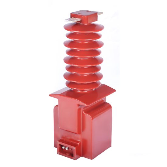
ZZW-35 11kV Cast-Resin Current Transformer for Substation Metering and Protection – IEC 61869-2 Certified
Introduction to the ZZW-35 Current Transformer
The ZZW-35 is a high-reliability, cast-resin insulated current transformer (CT) engineered for accurate current measurement and protective relaying in 11kV (IEC-rated) / 10kV (domestic system) medium-voltage distribution networks. Designed in strict compliance with IEC 61869-2 and GB/T 20840.2, this device leverages advanced vacuum pressure impregnation (VPI) epoxy resin technology to encapsulate its magnetic core and windings, ensuring long-term dielectric integrity and mechanical robustness under demanding environmental conditions.
Operating Principle and Cast-Resin Insulation Technology
The ZZW-35 functions on the principle of electromagnetic induction, where the primary conductor—typically a busbar or cable passing through the central aperture—carries the system current (Ip). This current generates a magnetic flux in the toroidal core, inducing a proportional secondary current (Is) in the wound secondary coil, standardized at 1 A or 5 A. The core is fabricated from grain-oriented electrical steel (GOES), selected for its low hysteresis loss and high permeability, which minimizes phase error and ensures accuracy across a wide load range (5%–120% of rated current). The entire assembly is encapsulated in cycloaliphatic epoxy resin via VPI casting, which eliminates air voids, prevents partial discharge (PD < 10 pC at 1.2 × Um/√3), and provides superior resistance to tracking, UV degradation, and thermal cycling. Unlike oil-filled alternatives, the solid insulation eliminates fire hazards, leakage risks, and maintenance-intensive fluid monitoring, making it ideal for indoor switchgear and compact outdoor substations.
Advantages Over Oil-Immersed and Dry-Type Alternatives
Compared to traditional oil-immersed CTs, the ZZW-35 offers significant safety and operational benefits. Its non-flammable epoxy matrix complies with IEC 60695 flammability standards, eliminating explosion risks in confined spaces. The absence of liquid insulation removes concerns about gasket aging, oil oxidation, and moisture ingress—common failure modes in oil units operating above 1,000 meters altitude. Relative to older dry-wound designs, the VPI-cast resin provides uniform electric field distribution, higher short-circuit withstand capability (rated up to 31.5 kA for 3 s), and stable performance under humidity levels up to 95% RH. Additionally, the monolithic construction resists vibration-induced winding displacement, a critical factor in industrial environments with heavy machinery or near railway traction systems. These attributes translate into a service life exceeding 25 years with minimal degradation in accuracy or insulation strength.
Typical Deployment Scenarios
The ZZW-35 is commonly deployed in 10kV/11kV ring main units (RMUs), pad-mounted transformers, and secondary substations serving commercial complexes, manufacturing plants, and utility distribution feeders. It supports dual secondary windings—one optimized for 0.5S class revenue metering and another for 5P20 class overcurrent protection—enabling simultaneous billing and fault detection without cross-interference. In renewable integration projects, such as solar farms or biogas plants connected to the 11kV grid, the ZZW-35’s low remanence core design ensures rapid saturation recovery after fault clearance, maintaining waveform fidelity during transient events. Its compact dimensions (height ≤ 380 mm, diameter ≤ 180 mm) facilitate retrofitting into legacy switchgear cabinets originally designed for smaller CTs, reducing upgrade costs.
Technical Specifications
The ZZW-35 is engineered to meet stringent electrical, thermal, and mechanical requirements for continuous operation in harsh distribution environments. All parameters are defined per IEC 61869-2 unless otherwise noted.
Rated Electrical Parameters
The primary rated voltage is 11 kV (Um = 12 kV), corresponding to a 10 kV nominal system voltage per Chinese utility practice. Standard current ratios include 50/1, 75/1, 100/1, 150/1, 200/1, 300/1, 400/1, 600/1, and 800/1 A, with custom ratios available upon request. Accuracy classes are designated per application: 0.2S or 0.5S for tariff metering (per IEC 62053-22), and 5P10, 5P15, or 5P20 for protection (per IEC 60044-1 legacy or IEC 61869-2 Annex B). Rated burden values range from 2.5 VA to 30 VA at cos φ = 0.8 lagging. The thermal short-time current rating is 20 kA for 1 s or 31.5 kA for 3 s, with a dynamic withstand current of 80 kA peak. Insulation coordination includes a power frequency withstand voltage of 28 kV rms for 1 minute and a lightning impulse withstand voltage of 75 kV peak (1.2/50 μs wave).
Environmental and Mechanical Ratings
The ZZW-35 is rated for both indoor and outdoor installation. Standard ambient temperature range is –25°C to +40°C, with an extended option for –40°C to +55°C using modified resin formulations. Relative humidity tolerance extends to 95% non-condensing at 40°C. The unit is suitable for altitudes up to 3,000 meters above sea level; above 1,000 m, derating factors apply per IEC 60071-2 (e.g., 1.1% reduction in withstand voltage per 100 m above 1,000 m). The housing features IP54 ingress protection when mounted vertically, with stainless steel mounting brackets and tinned copper secondary terminals rated for 600 V. Creepage distance exceeds 25 mm/kV (minimum 275 mm) for pollution degree III environments, per IEC 60815.
Core and Winding Construction Details
The magnetic circuit employs high-permeability GOES laminations (grade M4 or equivalent, thickness 0.27 mm), annealed after cutting to minimize residual stress. Secondary windings use enameled copper wire (Class H insulation, 180°C rating) with precise layer winding to control inter-turn capacitance and reduce high-frequency resonance. Each secondary is fully shielded with electrostatic screens between layers to suppress capacitive coupling from the primary. The VPI process involves degassing the resin mixture under vacuum, followed by pressure injection (0.6–0.8 MPa) into a preheated mold containing the core-winding assembly, ensuring complete impregnation and zero voids. Post-curing at 120°C for 8 hours yields a glass transition temperature (Tg) of ≥110°C, guaranteeing dimensional stability under thermal cycling.
Typical Applications
The ZZW-35 serves as a foundational component in modern medium-voltage infrastructure, enabling precise energy accounting and reliable fault isolation.
Substation Secondary Metering Systems
In urban distribution substations, the ZZW-35’s 0.2S-class secondary winding interfaces directly with digital revenue meters (e.g., IEC 62056-compliant AMI endpoints). Its low phase displacement (< ±10 minutes at 100% In) ensures compliance with regulatory accuracy mandates for commercial billing. For example, in a 10kV feeder supplying a shopping mall with peak demand of 600 A, a ZZW-35 with 600/1 A ratio and 10 VA burden delivers metering error within ±0.2% across 5–120% load range. The cast-resin body’s immunity to electromagnetic interference (EMI) from adjacent switchgear prevents signal corruption in smart metering architectures.
Industrial Power Distribution Networks
Heavy industries—such as cement plants, steel mills, and data centers—rely on the ZZW-35 for motor protection and load monitoring. Here, the 5P20 protection winding feeds numerical relays (e.g., Siemens 7SJ62) that require accurate current replication up to 20× rated current during short circuits. The CT’s high saturation voltage (≥150 V at 5P20) prevents core saturation during asymmetrical faults, ensuring relay coordination remains intact. In a 10kV motor control center with 400 kW induction motors, ZZW-35 units provide ground-fault detection sensitivity down to 0.5 A via residual current summation, enhancing personnel safety.
Renewable Energy Integration Points
Solar photovoltaic (PV) and wind farms connecting to the 11kV grid utilize the ZZW-35 at the point of common coupling (PCC). Its linear response during low-current operation (down to 1% In) enables accurate yield monitoring for performance-based incentives. During grid faults, the low remanence core (< 10% residual flux) allows rapid demagnetization, preventing false tripping of anti-islanding protection relays. In a 5 MW solar farm, dual-ratio ZZW-35 CTs (e.g., 400/1 for normal operation, 800/1 for fault duty) optimize both metering resolution and protection reliability without requiring external auxiliary CTs.
Rural and Suburban Distribution Feeders
Utility companies deploy the ZZW-35 on overhead and underground 10kV feeders serving dispersed residential loads. Its outdoor-rated housing withstands temperature swings from –30°C (winter) to +45°C (summer) without cracking or delamination. In rural China, where single-phase laterals are common, pole-mounted ZZW-35 units enable three-phase imbalance detection and theft prevention via remote terminal units (RTUs). The high creepage distance prevents flashovers during coastal fog or agricultural pesticide drift, reducing unplanned outages.
Microgrid and Islanded Operation Support
In campus microgrids operating in islanded mode, the ZZW-35 supports droop control and black-start sequencing. Its stable ratio error (< ±0.1% at 20–100% In) ensures precise active/reactive power sharing among distributed generators. During transitions between grid-connected and islanded states, the CT’s fast transient response (< 20 ms settling time) maintains voltage/frequency stability in the local network.
Compliance with International Standards
The ZZW-35 is certified to global and regional standards governing instrument transformer performance, safety, and interoperability.
IEC 61869-2 Certification Requirements
Per IEC 61869-2:2012 (Instrument transformers – Part 2: Additional requirements for current transformers), the ZZW-35 undergoes rigorous type tests including temperature rise (≤60 K for windings at 1.2× In), short-circuit withstand (thermal and dynamic), and accuracy verification across burden ranges. Ratio error and phase displacement are measured at 5%, 20%, 100%, and 120% of rated current using calibrated reference standards traceable to national metrology institutes. Partial discharge tests confirm levels below 10 pC at 1.2 × (12 kV/√3) = 8.3 kV, ensuring long-term insulation integrity. The standard also mandates marking requirements: model number, ratio, accuracy class, burden, polarity dot, and manufacturer ID must be permanently laser-etched on the resin body.
Alignment with GB/T 20840.2 Domestic Standard
GB/T 20840.2-2014 (identical adoption of IEC 61869-2) governs CT specifications in China. While technically harmonized, minor differences exist in test protocols: GB/T requires additional salt fog testing (1,000 hours per IEC 60068-2-11) for coastal installations and specifies a minimum short-time current rating of 20 kA/3 s for 10kV systems. The ZZW-35 exceeds these by offering 31.5 kA/3 s as standard. Furthermore, GB/T mandates dual marking of system voltage (10 kV) alongside IEC-rated voltage (11 kV) on nameplates—a requirement fulfilled on all units shipped to Chinese utilities.
Testing and Certification Documentation
Each ZZW-35 batch undergoes routine tests per IEC 61869-2 Clause 11: visual inspection, winding continuity, polarity verification, power frequency withstand (28 kV/1 min), and partial discharge. Type test reports (valid for 8 years) include accuracy plots, thermal imaging during overload, and impulse voltage waveforms. Certificates are issued by accredited labs (e.g., KEMA, CESI, or China Electric Power Research Institute) and include unique serial numbers traceable to manufacturing logs.
On-Site Testing Procedures
Post-installation verification ensures the ZZW-35 performs within specification before energization.
Insulation Resistance Test
Using a 2,500 V DC megohmmeter, measure insulation resistance between primary-to-secondary, primary-to-ground, and secondary-to-ground. Acceptance criterion: ≥1,000 MΩ at 20°C. Correct for temperature using RT2 = RT1 × 2(T1–T2)/10. Low readings indicate moisture ingress or resin cracking—requiring drying or replacement.
Turns Ratio and Polarity Verification
Apply 1–5 V AC to the secondary winding and measure induced primary voltage (open-circuit). Calculate ratio as Vs/Vp; compare to nameplate. Tolerance: ±0.5% for metering classes, ±1% for protection. Simultaneously verify reducing polarity: when primary current enters P1, secondary current exits S1. Use a DC battery and galvanometer—momentary deflection direction confirms polarity.
Power Frequency Withstand Voltage Test
Apply 28 kV rms (50 Hz) between primary and grounded secondary/housing for 1 minute. Monitor for flashover or excessive leakage current (< 1 mA). This validates insulation integrity after transport-induced microcracks. Perform only once in the CT’s lifetime to avoid cumulative dielectric stress.
Secondary Winding Resistance Measurement
Measure DC resistance of each secondary winding at 20°C using a Kelvin bridge. Compare to factory baseline (±5% tolerance). Significant increase indicates broken strands; decrease suggests shorted turns. Record values for future trending during preventive maintenance.
Excitation (Knee-Point) Characteristic Test
For protection-class windings, plot excitation curve by applying increasing AC voltage to secondary (primary open). Knee-point voltage (where slope drops 45°) must exceed 150 V for 5P20 class. This confirms adequate saturation margin during high-magnitude faults.
Preventive Maintenance Guide
Proactive maintenance extends service life and prevents unexpected failures.
Periodic Inspection Protocol
Conduct annual visual inspections: check for surface tracking, cracks, discoloration, or terminal corrosion. Clean housing with isopropyl alcohol if contaminated by dust or salt. Verify torque on secondary terminal screws (2.5 N·m for M6). Use infrared thermography during peak load to detect abnormal heating (>10 K above ambient)—indicative of high contact resistance or internal defects.
Maintenance Intervals and Diagnostic Schedule
Every 5 years, perform comprehensive diagnostics: repeat insulation resistance, excitation curve, and ratio tests. Compare results to baseline; degradation >10% warrants replacement. In high-pollution areas (e.g., chemical plants), shorten interval to 3 years. Maintain a logbook with test dates, ambient conditions, and technician IDs for audit compliance.
| Maintenance Task | Frequency | Acceptance Criteria |
|---|---|---|
| Visual Inspection | Annually | No cracks, tracking, or corrosion |
| Insulation Resistance | Every 5 years | ≥1,000 MΩ at 20°C |
| Ratio & Polarity | Every 5 years | Within ±0.5% (metering), ±1% (protection) |
| Excitation Curve | Every 5 years (protection windings) | Knee-point ≥150 V for 5P20 |
Conclusion
The ZZW-35 11kV cast-resin current transformer represents a benchmark in medium-voltage instrumentation, combining decades of engineering refinement with modern materials science. Its VPI epoxy resin encapsulation delivers unmatched dielectric reliability, eliminating the fire and environmental hazards associated with oil-filled alternatives while providing superior mechanical stability in seismic zones (rated for 0.3g horizontal acceleration per IEC 60068-2-57). The use of GOES core material ensures metrological precision across the full operational spectrum—from light-load metering at 5% of rated current to high-fault protection at 20× overcurrent—without compromising saturation characteristics. Full compliance with IEC 61869-2 and GB/T 20840.2 guarantees interoperability with global protection and metering ecosystems, while rigorous type testing validates performance under extreme thermal, electrical, and environmental stressors. With a design life of 25–30 years and minimal maintenance requirements, the ZZW-35 reduces total cost of ownership for utilities and industrial operators alike. Its adaptability to diverse applications—from dense urban substations to remote renewable sites—cements its role as a cornerstone of resilient, accurate, and safe medium-voltage power systems worldwide.