Article Content
CT-35K 33kV Cast-Resin Current Transformer for Substation Metering and Protection – IEC 61869-2 Certified
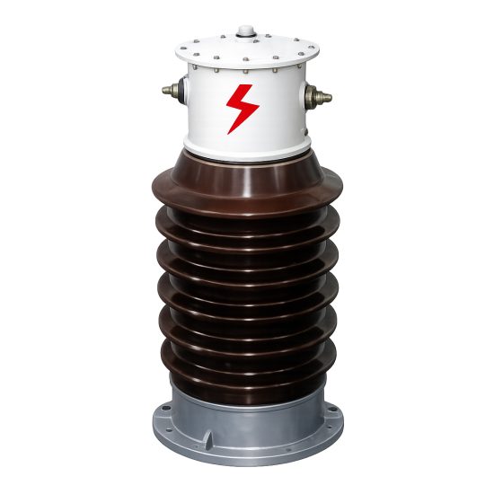
Introduction to the CT-35K Current Transformer
The CT-35K is a high-reliability, cast-resin insulated current transformer engineered for operation in 33 kV (IEC-rated) or 35 kV (domestic system) medium-voltage networks. Designed in strict compliance with IEC 61869-2 and GB/T 20840.2, this device enables accurate current measurement and dependable protective relay coordination in utility substations, industrial facilities, and renewable energy interconnection points. Its robust construction leverages vacuum pressure impregnation (VPI) epoxy resin technology to encapsulate a grain-oriented electrical steel (GOES) core, ensuring long-term dielectric integrity and mechanical stability under thermal and electrical stress.
Operating Principle of Cast-Resin Insulation
Cast-resin insulation in the CT-35K employs a two-component cycloaliphatic epoxy resin system processed under vacuum and pressure to eliminate voids and moisture ingress. This VPI technique fully encapsulates the primary conductor, secondary windings, and magnetic core, creating a monolithic structure with superior tracking resistance (compliant with IEC 60587) and hydrophobic surface properties. Unlike oil-filled alternatives, the solid dielectric eliminates fire hazards, environmental contamination risks, and maintenance-intensive oil sampling. The resin’s coefficient of thermal expansion closely matches that of copper and steel, minimizing internal stresses during thermal cycling from –40°C to +40°C ambient conditions. Dielectric strength exceeds 20 kV/mm, supporting the required power frequency withstand voltage of 70 kV rms for 1 minute between primary and ground, as mandated by IEC 61869-2 for 33 kV systems.
Advantages Over Oil-Immersed Designs
The CT-35K’s cast-resin construction offers significant operational advantages over traditional oil-immersed current transformers. First, it is inherently maintenance-free—no oil level checks, degassing, or periodic dielectric testing are required. Second, its compact footprint (typically 30% smaller than equivalent oil units) facilitates installation in space-constrained indoor switchgear or pole-mounted configurations. Third, the absence of flammable fluids allows deployment in fire-sensitive environments such as underground substations or chemical plants without additional containment measures. Additionally, the solid insulation exhibits negligible aging under partial discharge activity (<5 pC at 1.2 × Ur), contributing to a service life exceeding 30 years. Finally, the unit is immune to oil leakage, which can compromise insulation performance and cause secondary circuit faults in legacy designs.
Typical Application Overview
The CT-35K is deployed across diverse medium-voltage infrastructure where precision and reliability are non-negotiable. In utility transmission substations, it provides Class 0.2S metering accuracy for revenue-grade energy billing and Class 5P20 protection characteristics for feeder overcurrent relays. Industrial users integrate the CT-35K into motor control centers (MCCs) rated up to 35 kV to monitor large induction motors and enable differential protection schemes. Renewable energy projects—particularly solar farms with 35 kV collector systems—rely on its stable ratio error performance under harmonic-rich waveforms. Rural distribution networks benefit from its outdoor-rated housing (IP54) and resistance to pollution (creepage distance ≥ 25 mm/kV).
Technical Specifications
The CT-35K is engineered to meet stringent electrical and environmental requirements for 33 kV systems, with design margins accommodating 35 kV domestic network voltages. All parameters align with IEC 61869-2 Clause 5 and GB/T 20840.2 Table 3.
| Parameter | Value |
|---|---|
| Rated System Voltage (Ur) | 33 kV (IEC), 35 kV (Domestic) |
| Rated Insulation Level | LI 170 kV / AC 70 kV (1 min) |
| Primary Current (Ipr) | 50 A to 3000 A (standard ratios) |
| Secondary Current (Isr) | 1 A or 5 A |
| Metering Accuracy Class | 0.2S, 0.5S (per IEC 61869-2) |
| Protection Accuracy Class | 5P10, 5P20, 10P10, 10P20 |
| Rated Burden (Metering) | 2.5 VA to 15 VA @ cos φ = 0.8 |
| Rated Burden (Protection) | 15 VA to 30 VA @ cos φ = 0.8 |
| Short-Time Thermal Current | 25 kA for 1 s (Ith) |
| Dynamic Withstand Current | 62.5 kA peak (Idyn) |
| Ambient Temperature Range | –40°C to +40°C |
| Altitude Limit | ≤ 1000 m (derating above 1000 m) |
| Relative Humidity | Up to 95% non-condensing |
| Creepage Distance | ≥ 825 mm (25 mm/kV × 33 kV) |
Electrical Performance Parameters
The CT-35K delivers precise metrological performance under defined operating conditions. For metering applications, Class 0.2S guarantees a composite error ≤ ±0.2% at 20% to 120% of rated primary current, with phase displacement ≤ ±10 minutes. Protection classes (e.g., 5P20) ensure ≤ ±5% current error at 20× rated current, enabling reliable relay operation during fault conditions. The GOES core (grade M4, thickness 0.27 mm) minimizes hysteresis losses and maintains low excitation current—critical for avoiding saturation during asymmetrical faults. Secondary winding resistance is tightly controlled (±2% tolerance) to ensure burden compatibility with modern digital relays and meters. All units undergo factory calibration at 50 Hz and 60 Hz to support global deployment.
Environmental and Mechanical Ratings
Designed for both indoor and outdoor service, the CT-35K features a UV-stabilized cycloaliphatic resin housing rated IP54 per IEC 60529. The flanged base conforms to IEC 61869-2 dimensional standards for interchangeability with existing 33 kV switchgear. Mechanical load capacity supports 500 N transverse force on the primary terminal without deformation. At altitudes exceeding 1000 m, the power frequency withstand voltage is derated by 1% per 100 m above sea level, while lightning impulse withstand remains unchanged. The unit withstands seismic Zone 2 (0.25g horizontal acceleration) per IEC 60068-2-57, making it suitable for earthquake-prone regions.
Typical Applications
The CT-35K serves critical roles across multiple sectors requiring accurate current transformation at 33/35 kV levels.
Substation Secondary Metering
In transmission and distribution substations, the CT-35K provides Class 0.2S current signals to revenue meters, SCADA RTUs, and power quality analyzers. Its low phase error ensures accurate calculation of real/reactive energy even under distorted waveforms (THD ≤ 15%). For example, in a 35 kV urban substation feeding commercial districts, dual-secondary CT-35K units supply one winding to an AMI meter (0.2S, 5 VA) and another to a multifunction relay (5P20, 15 VA), eliminating the need for separate metering and protection transformers. The cast-resin body resists tracking from salt fog in coastal installations, maintaining insulation integrity over decades.
Industrial Power Distribution
Heavy industries—such as mining, cement, and petrochemical plants—deploy the CT-35K on 35 kV motor feeders rated up to 10 MW. Here, 5P20 accuracy ensures instantaneous overcurrent relays trip within 30 ms during locked-rotor faults, while the 25 kA thermal withstand rating survives downstream short circuits. The compact design fits within ANSI C37.20.2 metal-clad switchgear, and the epoxy housing resists chemical vapors that degrade porcelain insulators. In arc furnace applications, the CT-35K’s core is oversized to handle DC offset without saturation during frequent switching transients.
Renewable Energy Integration
Solar photovoltaic (PV) farms with 35 kV collector systems use the CT-35K for both generation metering and anti-islanding protection. The transformer’s linearity under harmonic currents (up to 13th order) ensures accurate energy yield reporting to grid operators. During cloud-induced ramp events, the fast response time (<10 ms) supports dynamic reactive power control via STATCOMs. Wind farms employ CT-35K units on turbine step-up transformers, where the –40°C cold-start capability prevents brittle fracture in arctic climates.
Rural and Suburban Distribution Networks
Utility-owned pole-top or pad-mounted reclosers in rural grids integrate the CT-35K for sectionalizing and fault location. The IP54 enclosure withstands dust storms and monsoon rains, while the high creepage distance prevents flashovers in polluted environments (e.g., agricultural ammonia exposure). In suburban ring-main units, single-core CT-35K models monitor load balancing across three-phase feeders, feeding data to distribution management systems (DMS) for outage prediction.
Compliance with International Standards
The CT-35K is certified to both international and Chinese national standards, ensuring global interoperability and regulatory acceptance.
IEC 61869-2 Compliance Details
Per IEC 61869-2:2012, the CT-35K meets all requirements for electromagnetic instrument transformers. Key verifications include: temperature rise tests (≤ 55 K for windings at 1.2 × Ipr), short-circuit withstand validation (25 kA/1s without damage), and accuracy verification across 1% to 120% Ipr. The standard mandates that protection-class CTs maintain specified errors at rated symmetrical short-circuit current factor (e.g., 20 for 5P20). Dielectric tests follow Table 2 of IEC 61869-2, with 70 kV AC applied for 60 seconds between primary and earthed parts. Partial discharge measurements are conducted at 1.2 × Ur/√3, with limits of 10 pC for resin-insulated CTs.
GB/T 20840.2 Alignment
GB/T 20840.2-2014 (equivalent to IEC 61869-2) governs domestic Chinese deployments. While largely harmonized, GB/T specifies slightly higher creepage distances (31 mm/kV vs. IEC’s 25 mm/kV) for heavy pollution zones—addressed in the CT-35K’s 825 mm minimum creepage. GB/T also requires altitude correction factors up to 3000 m, whereas IEC defaults to 1000 m. Factory tests per GB/T include additional impulse voltage tests with chopped waves (1.2/50 μs, 170 kV peak) to simulate switching surges. All CT-35K units destined for China undergo third-party certification by CEPREI or SGS to confirm GB/T compliance.
Key Differences Between IEC and Domestic Standards
Although IEC 61869-2 and GB/T 20840.2 share core principles, critical distinctions affect design. GB/T mandates stricter short-circuit duration (3 s vs. IEC’s 1–3 s default), requiring enhanced thermal mass in the CT-35K’s primary conductor. Additionally, GB/T defines accuracy classes using “composite error” rather than IEC’s “current error + phase displacement,” though numerical limits are identical. Environmental testing under GB/T includes sand-dust exposure (IP6X) not required by IEC. Despite these differences, the CT-35K’s modular design accommodates both standards through minor core/burden adjustments without altering the resin mold.
On-Site Testing Procedures
Post-installation verification ensures the CT-35K performs within specifications before energization.
Insulation Resistance Test
Using a 2500 V DC megohmmeter, measure insulation resistance between primary winding and ground, and between secondary windings and ground. Acceptance criteria: ≥ 1000 MΩ at 20°C. Correct for temperature using RT2 = RT1 × 2(T1–T2)/10. Values below 500 MΩ indicate moisture ingress or resin cracking, requiring drying or replacement. Perform before and after dielectric tests to detect insulation degradation.
Turns Ratio Test
Apply a low-voltage AC source (5–10 V) to the primary and measure secondary voltage. Calculate actual ratio = Vp/Vs. Compare to nameplate ratio; tolerance must be within ±0.2% for metering classes and ±1% for protection classes. Use a dedicated turns ratio tester (e.g., Omicron CT Analyzer) for automated comparison. Deviations >2% suggest inter-turn shorts or incorrect tap selection.
Polarity Test
Verify reducing polarity per IEC 61869-2 Figure 3. Connect a 1.5 V DC battery to primary (positive to P1), and a center-zero galvanometer to secondary (positive to S1). Momentary closure should produce a positive kick. Incorrect polarity causes relay misoperation—e.g., differential protection tripping on load current. Document results with timestamped photos for commissioning records.
Power Frequency Withstand Voltage Test
Apply 70 kV rms at 50 Hz for 60 seconds between primary and grounded enclosure. Use a calibrated test transformer with overcurrent trip (≤ 10 mA). No flashover or disruptive discharge is permitted. For field tests, reduce voltage to 80% (56 kV) if equipment history is unknown. Always discharge primary capacitance post-test using a grounding stick.
Excitation (Saturation) Characteristic Test
Inject increasing AC voltage (0–500 V) into secondary winding while measuring excitation current. Plot knee-point voltage per IEC 60044-1 Annex B. For 5P20 CTs, knee-point must exceed 20 × (Isr × Zb + Rct). Typical CT-35K knee-point: ≥ 400 V at 1 A secondary. Low knee-point indicates core saturation risk during faults.
Preventive Maintenance Guide
Though cast-resin CTs require minimal upkeep, scheduled inspections extend service life.
Periodic Inspection Protocol
Conduct annual visual inspections: check for resin cracks, tracking marks, or terminal corrosion. Clean housing with deionized water if salt/pollution deposits exceed 0.1 mg/cm². Verify secondary terminal tightness (torque: 2.5 N·m for M6 screws). Every 5 years, repeat insulation resistance and turns ratio tests. After any system fault >10 kA, perform excitation curve analysis to detect core damage. Replace units showing >10% ratio drift or insulation resistance <200 MΩ.
Maintenance Intervals and Fault Diagnosis
| Interval | Action | Fault Indicator |
|---|---|---|
| Annually | Visual inspection, terminal check | Cracks, discoloration, loose lugs |
| Every 5 years | Insulation resistance, ratio test | Rins < 500 MΩ, ratio error >1% |
| Post-fault | Excitation curve, polarity recheck | Knee-point drop >15%, polarity reversal |
| Every 10 years | Partial discharge scan (if available) | PD > 20 pC at 1.2 × Ur/√3 |
Common failure modes include secondary open-circuit during operation (causing dangerous overvoltages) and moisture ingress through terminal box seals. Always short-circuit secondary terminals before disconnecting meters/relays.
Conclusion
The CT-35K 33 kV cast-resin current transformer represents a benchmark in medium-voltage instrumentation, combining IEC 61869-2 and GB/T 20840.2 compliance with field-proven reliability. Its VPI epoxy resin insulation eliminates the fire and environmental risks associated with oil-filled units, while the GOES core ensures metrological precision across metering (0.2S) and protection (5P20) applications. Rigorous factory testing—including dielectric withstand, accuracy verification, and short-circuit validation—guarantees performance under the most demanding conditions, from arctic substations to desert solar farms. With a design life of 25–30 years and minimal maintenance requirements, the CT-35K reduces total cost of ownership while enhancing grid safety and measurement integrity. Its adaptability to both 33 kV international and 35 kV domestic systems makes it a versatile solution for global utilities and industrial operators seeking future-proof instrumentation. As power networks evolve toward smarter, more resilient architectures, the CT-35K’s robust engineering ensures seamless integration with next-generation protection and monitoring systems.