Article Content
IEC 61869-3 Certified 11kV Voltage Transformer JDZW-10R for Metering & Protection Applications
Introduction to the JDZW-10R Voltage Transformer
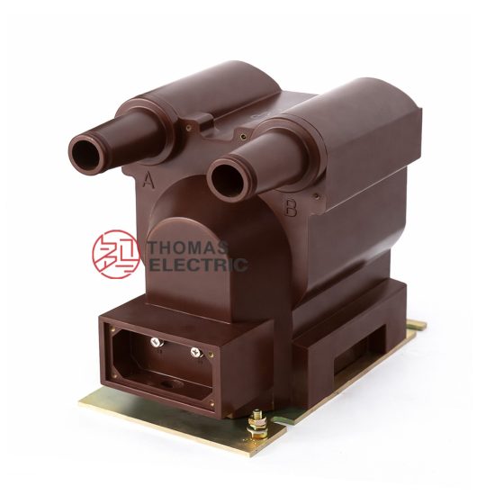
The JDZW-10R is a single-phase, indoor/outdoor rated, cast-resin insulated voltage transformer (VT) designed for accurate voltage measurement and reliable protective relay operation in medium-voltage power systems operating at 11kV (IEC standard) or 10kV (domestic Chinese system nominal voltage). As part of the instrument transformer family governed by IEC 61869-3 and GB/T 20840.3, this device converts high primary system voltages to standardized secondary values—typically 100 V or 100/√3 V—for interfacing with metering instruments, protective relays, and monitoring equipment.
Operating Principle of Cast-Resin Insulation
Cast-resin insulation in the JDZW-10R employs vacuum pressure impregnation (VPI) of cycloaliphatic epoxy resin around the primary and secondary windings wound on a grain-oriented electrical steel (GOES) core. This process eliminates air voids and moisture ingress pathways, resulting in a monolithic, non-hygroscopic dielectric structure. The resin’s high tracking resistance (>600 V per IEC 60112) and thermal class F (155°C) rating ensure stable performance under continuous load and transient overvoltages. Unlike oil-filled units, the solid insulation provides inherent fire safety (non-flammable), eliminates leakage risks, and requires no periodic oil sampling or conservator maintenance.
Advantages Over Oil-Immersed Designs
Compared to traditional oil-immersed VTs, the JDZW-10R offers significant operational and safety benefits. Its dry-type construction eliminates fire hazards in confined switchgear rooms, complies with stringent environmental regulations (no PCB or mineral oil disposal), and reduces lifecycle costs through minimal maintenance. The compact footprint—enabled by higher dielectric strength of epoxy resin (~20 kV/mm vs. ~10 kV/mm for oil)—facilitates integration into space-constrained ring main units (RMUs) and prefabricated substations. Additionally, the absence of oil prevents gas accumulation that could compromise insulation integrity during partial discharge events.
Typical Application Overview
The JDZW-10R is engineered for dual-purpose use: precision metering (accuracy classes 0.2 or 0.5) and protection (3P or 6P classes). It is commonly deployed in 11kV distribution substations, industrial plant switchyards, wind/solar farm collector systems, and rural electrification networks. Its robust design withstands switching surges (BIL 75 kV) and temporary overvoltages up to 1.9 × Un/√3 for 8 hours, ensuring continuity during single-phase-to-ground faults prevalent in unearthed or resonant-earthed systems.
Technical Specifications
The JDZW-10R adheres to strict dimensional, electrical, and thermal parameters defined by international and national standards. Below is a comprehensive specification table followed by environmental service conditions.
| Parameter | Value |
|---|---|
| Primary Voltage (Up) | 11 kV (IEC) / 10 kV (GB) |
| Secondary Voltage (Us) | 100 V or 100/√3 V |
| Voltage Ratio | 11000/100 V or 11000/100/√3 V |
| Accuracy Class (Metering) | 0.2, 0.5 |
| Accuracy Class (Protection) | 3P, 6P |
| Rated Output (Burden) | 10–100 VA (per accuracy class) |
| Insulation Level (Um) | 12 kV |
| Lightning Impulse Withstand (BIL) | 75 kV peak |
| Power Frequency Withstand | 28 kV rms, 1 min |
| Thermal Limit Output | ≥150% of rated burden continuously |
| Core Material | Grain-Oriented Electrical Steel (GOES), 0.3 mm thickness |
| Insulation System | VPI cycloaliphatic epoxy resin, UL 94 V-0 rated |
| Polarity | Reduced polarity (standard) |
| Weight | Approx. 45 kg |
| Dimensions (H×W×D) | 680 × 220 × 220 mm |
Standard Service Conditions
The JDZW-10R is rated for operation under IEC 60060-1 standard atmospheric conditions: ambient temperature range of –25°C to +40°C, relative humidity ≤95% (non-condensing), and installation altitude ≤1000 m above sea level. For altitudes exceeding 1000 m, derating factors apply per IEC 60071-2: a 1% reduction in withstand voltage per 100 m above 1000 m is required. The unit is suitable for both indoor switchgear panels and outdoor pole-mounted or pad-mounted installations when housed in IP44-rated enclosures.
Accuracy and Burden Characteristics
Accuracy class defines permissible ratio and phase errors under specified burdens. For example, a JDZW-10R rated 0.2 class must maintain ratio error ≤±0.2% and phase displacement ≤±10 minutes at 25–100% of rated burden (e.g., 30 VA). Protection-class units (3P/6P) prioritize stability under fault conditions: a 3P VT limits ratio error to ±3% at 5%–100% of rated voltage and up to 100% of rated burden. Burden compatibility must be verified during system design—exceeding rated VA causes increased errors and potential overheating.
Typical Applications
The JDZW-10R serves critical roles across diverse power infrastructure segments due to its dual metering/protection capability, environmental resilience, and long service life.
Substation Secondary Metering
In 11kV primary substations, the JDZW-10R supplies scaled-down voltages to revenue-class kWh meters, demand recorders, and SCADA RTUs. Its 0.2-class accuracy ensures billing compliance per regulatory requirements (e.g., China’s DL/T 448). Installed on each phase in three-phase systems, it enables vector group verification and power factor monitoring. The cast-resin body resists contamination from dust and salt fog in coastal or industrial zones, maintaining dielectric integrity without cleaning cycles required for oil-filled counterparts.
Industrial Power Distribution
Large manufacturing facilities—such as steel mills, chemical plants, and data centers—use JDZW-10R units for internal energy accounting and motor protection schemes. In arc furnace or variable-frequency drive (VFD) environments, harmonic distortion can induce core saturation; however, the GOES core’s low hysteresis loss and the resin’s damping effect mitigate harmonic amplification. Secondary outputs feed multifunction relays (e.g., over/under-voltage, loss-of-potential) with 6P-class reliability during grid disturbances.
Renewable Energy Integration
Solar photovoltaic (PV) farms and onshore wind turbines employ JDZW-10R VTs at the 11kV collector bus for grid synchronization, anti-islanding detection, and revenue metering. The unit’s immunity to DC offset—common during inverter faults—and fast transient response (<20 ms rise time) support precise fault ride-through (FRT) compliance. Its maintenance-free nature reduces O&M visits in remote sites, while UV-stabilized resin housings endure prolonged solar exposure without embrittlement.
Rural and Suburban Distribution Networks
In rural electrification projects, the JDZW-10R is mounted on utility poles or ground platforms to monitor voltage profiles along lightly loaded feeders. Its ability to operate accurately at 20% of rated burden addresses low-load scenarios typical in agricultural areas. The absence of oil eliminates theft and spillage risks, while the lightweight design simplifies manual handling during deployment. Compatibility with legacy electromechanical relays ensures seamless retrofitting in aging infrastructure.
Compliance with International Standards
The JDZW-10R is engineered to satisfy both global and Chinese regulatory frameworks, ensuring interoperability and safety across markets.
IEC 61869-3 Compliance Details
IEC 61869-3 specifies performance, testing, and marking requirements for inductive voltage transformers. The JDZW-10R meets all clauses, including:
– Clause 5.3: Insulation coordination (Um = 12 kV, BIL = 75 kV)
– Clause 6.2: Accuracy verification under sinusoidal waveforms (THD < 2%)
- Clause 7.4: Temperature rise limits (≤60 K for windings at rated burden)
- Clause 8.1: Partial discharge levels <10 pC at 1.2 × Um/√3
Certification includes type tests (e.g., short-circuit withstand, thermal stability) and routine tests (ratio, polarity, insulation resistance) performed in accredited laboratories.
Alignment with GB/T 20840.3
GB/T 20840.3 is China’s national adoption of IEC 61869-3 with minor modifications. Key alignments include identical accuracy classes, insulation levels, and test methodologies. However, GB/T mandates additional requirements:
– Altitude correction for installations >1000 m (mandatory derating)
– Enhanced seismic withstand (0.3g horizontal acceleration)
– Localized labeling in Chinese characters alongside English
Manufacturers must obtain China Compulsory Certification (CCC) demonstrating conformity to GB/T 20840.3 before domestic sales.
Key Differences Between IEC and Domestic Standards
While technically harmonized, practical differences exist. IEC 61869-3 permits optional residual voltage windings for earth-fault detection, whereas GB/T 20840.3 often requires them in unearthed systems. Additionally, GB/T specifies stricter creepage distance: ≥20 mm/kV for polluted environments (vs. IEC’s 18 mm/kV). These nuances necessitate region-specific design validation—Duomatech produces JDZW-10R variants optimized for EU, ASEAN, and Chinese grids respectively.
On-Site Testing Procedures
Post-installation commissioning tests verify integrity and performance per IEC 61869-3 Clause 10.
Insulation Resistance Test
Using a 2500 V DC megohmmeter, measure insulation resistance between primary winding and ground, secondary winding and ground, and inter-winding. Acceptance criteria: ≥1000 MΩ at 20°C. Values below 500 MΩ indicate moisture ingress or resin cracking. Temperature correction applies: RT2 = RT1 × 2(T1–T2)/10. Perform before and after dielectric tests to detect insulation degradation.
Turns Ratio Test
Apply 100–200 V AC to the primary and measure secondary voltage with a calibrated voltmeter (±0.1% accuracy). Calculate actual ratio: Up/Us. Tolerance must be within ±0.2% for 0.2-class units. Use a dedicated ratio bridge (e.g., Omicron CT Analyzer) for automated verification. Deviations >0.5% suggest turn-to-turn shorts or incorrect tap selection.
Polarity Test
Verify reduced polarity using the DC kick method: connect a 6–12 V battery across primary terminals (H1+, H2–). Momentarily close the circuit while observing a center-zero galvanometer connected to secondary (X1+, X2–). A positive deflection confirms correct polarity. Incorrect polarity reverses phasor relationships, causing metering errors and relay misoperation.
Power Frequency Withstand Voltage Test
Apply 28 kV rms (50 Hz) between primary and grounded tank/secondary for 60 seconds. Monitor for flashover, excessive current (>10 mA), or audible discharge. The test validates insulation integrity after transport-induced mechanical stress. Reduce voltage gradually post-test to avoid resonant overvoltages. Never perform if ambient humidity exceeds 80%.
Open-Circuit Characteristic Test
With secondary open, ramp primary voltage from 0 to 190% of Un (20.9 kV) in 10% steps. Record excitation current. A sharp current rise above 120% Un indicates core saturation—acceptable only if within thermal limits. This test detects shorted turns: abnormal magnetizing current at low voltages (<50% Un) signals inter-turn faults.
Preventive Maintenance Guide
Although cast-resin VTs require less maintenance than oil-filled types, scheduled inspections extend service life beyond 25 years.
Periodic Inspection Protocol
Conduct annual visual and electrical checks:
– Inspect housing for cracks, tracking, or UV degradation
– Clean terminals with isopropyl alcohol; torque lugs to 15 N·m
– Verify grounding continuity (<0.1 Ω resistance)
- Perform insulation resistance and ratio tests biennially
Document all readings in asset management systems to trend degradation. Immediate replacement is warranted if partial discharge exceeds 20 pC during live testing.
Maintenance Intervals and Fault Diagnosis
Adhere to the following schedule:
| Interval | Action |
|---|---|
| Annually | Visual inspection, terminal cleaning, IR test |
| Every 5 Years | Full commissioning suite (ratio, polarity, PD, thermal scan) |
| After Major Fault | Dielectric tests and core excitation check |
Common faults include:
– **Ratio drift**: Caused by turn shorts; confirmed via open-circuit test
– **High IR leakage**: Indicates surface contamination; clean with deionized water
– **Abnormal heating**: Suggests excessive burden; verify connected load ≤ rated VA
Never attempt field repair—replace the entire unit due to monolithic resin construction.
Conclusion
The JDZW-10R 11kV cast-resin voltage transformer represents a benchmark in medium-voltage instrumentation, combining IEC 61869-3 and GB/T 20840.3 compliance with robust engineering for demanding metering and protection applications. Its VPI epoxy resin insulation eliminates fire and environmental hazards associated with oil-filled alternatives, while the GOES core ensures high accuracy and low losses across a wide operating range. With a proven service life of 25–30 years under standard conditions, the JDZW-10R delivers exceptional lifecycle value through minimal maintenance, resistance to pollution and humidity, and consistent performance in both urban substations and remote renewable sites. Rigorous factory and field testing protocols guarantee reliability, making it a preferred choice for utilities and industrial operators prioritizing safety, accuracy, and long-term operational stability. When integrated with modern digital relays and smart meters, the JDZW-10R forms a critical link in the intelligent grid infrastructure of the future.