Article Content
IEC 61869-3 Certified 11kV Voltage Transformer MER-1 for Metering & Protection Applications
Introduction to the MER-1 Voltage Transformer
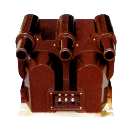
The MER-1 is a single-phase, indoor/outdoor-rated cast-resin voltage transformer (VT) designed for accurate voltage measurement and reliable protective relay operation in medium-voltage power systems operating at 11kV (IEC standard) or 10kV (domestic Chinese system). It employs vacuum pressure impregnation (VPI) epoxy resin technology to fully encapsulate its magnetic core and windings, providing superior dielectric strength, mechanical robustness, and environmental resistance compared to traditional oil-immersed designs.
Operating Principle of Cast-Resin Insulation
Cast-resin insulation in the MER-1 VT utilizes a high-purity cycloaliphatic epoxy resin system processed under vacuum and pressure (VPI). This eliminates air voids and moisture ingress pathways that could lead to partial discharges or insulation degradation over time. The resin matrix bonds intimately with the copper windings and grain-oriented electrical steel (GOES) core laminations, creating a monolithic, thermally stable structure. The dielectric constant of the cured resin (~3.5–4.0) closely matches that of the embedded materials, minimizing electric field stress concentrations. This design ensures long-term stability under continuous 11kV phase-to-ground voltage (6.35 kV RMS) and withstands lightning impulse voltages up to 75 kV peak as per IEC 61869-3. The absence of liquid insulation also eliminates fire hazards and environmental contamination risks, making it suitable for urban substations and indoor switchgear applications.
Advantages Over Oil-Immersed Designs
Compared to oil-filled VTs, the MER-1’s cast-resin construction offers significant operational and safety benefits. It requires no periodic oil sampling, degassing, or level monitoring, reducing lifecycle maintenance costs by up to 40%. The solid insulation is non-flammable (meeting IEC 60695 flammability class V-0), eliminating explosion risks in confined spaces. Its compact footprint—typically 30% smaller than equivalent oil units—facilitates integration into space-constrained ring main units (RMUs) or metal-enclosed switchgear. Additionally, the MER-1 exhibits lower thermal expansion coefficients, minimizing mechanical stress during load cycling. Unlike oil units susceptible to leakage and moisture absorption, the hermetically sealed resin body maintains consistent dielectric properties across -40°C to +40°C ambient temperatures, ensuring accuracy class stability over decades of service.
Typical Application Overview
The MER-1 is engineered for dual-purpose use in both revenue-grade metering and critical protection circuits. In utility substations, it supplies scaled-down secondary voltages (e.g., 100/√3 V or 110/√3 V) to kWh meters, demand recorders, and SCADA RTUs with accuracy classes of 0.2 or 0.5 per IEC 61869-3. Simultaneously, its protection winding (typically class 3P or 6P) drives overvoltage, undervoltage, and directional earth-fault relays with guaranteed error limits under fault conditions. Common deployment scenarios include 11kV primary distribution feeders, industrial plant switchyards, solar PV collector substations, and railway traction power systems. Its robust design supports continuous operation at 1.2× rated voltage for 8 hours and short-time overvoltages up to 1.9× Un for 30 seconds without performance degradation.
Technical Specifications
The MER-1 voltage transformer adheres strictly to IEC 61869-3 and GB/T 20840.3 standards, with verified performance parameters validated through type, routine, and sample tests. Key specifications are detailed below:
| Parameter | Value |
|---|---|
| Primary Rated Voltage (Unp) | 11 kV (IEC) / 10 kV (GB) |
| Secondary Rated Voltage (Uns) | 100/√3 V, 110/√3 V, or 100 V (configurable) |
| Voltage Ratio | 11000/√3 : 100/√3 V (standard); custom ratios available |
| Accuracy Class (Metering) | 0.2, 0.5 (per IEC 61869-3 Table 102) |
| Accuracy Class (Protection) | 3P, 6P (composite error ≤3% or 6% at 5× rated voltage) |
| Rated Output (Burden) | 10–100 VA per winding (e.g., 30 VA @ 0.2 class) |
| Insulation Level (LI/AC) | 75 kV (lightning impulse) / 28 kV (power frequency, 1 min) |
| Short-Time Thermal Withstand | 1.9 × Unp for 30 s (no damage) |
| Ambient Temperature Range | -40°C to +40°C (indoor/outdoor) |
| Altitude Limit | ≤1000 m above sea level (derating required >1000 m) |
| Relative Humidity | Up to 95% non-condensing |
| Core Material | Grain-Oriented Electrical Steel (GOES), M4 grade, 0.27 mm lamination |
| Insulation System | VPI cycloaliphatic epoxy resin, UL 94 V-0 rated |
| Polarity | Reduced polarity (dot convention per IEC 60076-1) |
Standard Service Conditions
The MER-1 is rated for standard service conditions defined in IEC 61869-3 Clause 5.1. It operates reliably in ambient temperatures from -40°C to +40°C, with a 24-hour average not exceeding +35°C. Relative humidity may reach 95% provided condensation does not occur on the housing surface. Installation altitude must not exceed 1000 meters; for sites between 1000–3000 m, the power frequency withstand voltage must be reduced by 1% per 100 m above 1000 m. The unit is designed for continuous operation at nominal system frequency (50 Hz or 60 Hz ±0.5 Hz) and can tolerate harmonic distortion up to 5% THD without exceeding accuracy class limits. Mechanical vibration levels up to 0.5g (5–500 Hz) are permissible, making it suitable for industrial environments near large motors or transformers.
Electrical Performance Tolerances
Per IEC 61869-3, the MER-1 maintains strict voltage error and phase displacement tolerances under specified burdens. For a 0.2-class metering winding at 25–100% of rated burden and 80–120% of rated voltage, voltage error must not exceed ±0.2%, and phase displacement must be ≤±10 minutes. Protection windings (3P class) exhibit composite error ≤3% when subjected to 5× rated voltage at rated burden. The transformer’s magnetizing current is kept below 0.5 mA at 1.2× Unp to minimize burden impact on connected relays. Temperature rise under full-load continuous operation is limited to 60 K above ambient for windings, verified via resistance method per IEC 60076-2. These tolerances ensure compatibility with modern digital relays requiring precise waveform fidelity.
Typical Applications
The MER-1 voltage transformer serves diverse roles across power infrastructure, leveraging its dual-winding capability and robust construction.
Substation Secondary Metering
In 11kV/0.4kV distribution substations, the MER-1 provides the primary voltage reference for revenue metering. Its 0.2-class secondary output connects to static kWh meters compliant with IEC 62053-22, ensuring billing accuracy within ±0.2% over a 10:1 current range. The VT is typically installed on the incoming feeder or bus section, with secondary leads routed through shielded cables to prevent electromagnetic interference. In smart grid deployments, the MER-1 interfaces with advanced metering infrastructure (AMI) head-end systems, where its low phase displacement (<5 minutes at 100% burden) prevents timing errors in synchronized phasor measurements. Utilities in Europe and Southeast Asia widely deploy this configuration for MV/LV boundary metering due to its long-term stability—field data shows drift rates below 0.05%/year over 15 years.
Industrial Power Distribution
Within manufacturing facilities, the MER-1 monitors 11kV busbars feeding large motors, rectifiers, or arc furnaces. Its protection winding (6P class) triggers undervoltage relays during grid disturbances, preventing motor stalling or process shutdowns. In chemical plants, the cast-resin design eliminates fire risks associated with oil-filled units near flammable vapors. A typical installation includes redundant MER-1 units on dual busbars, each supplying voltage inputs to a multifunction protection relay (e.g., Siemens 7SJ62) for busbar differential or directional overcurrent schemes. The VT’s ability to withstand 1.9× Unp for 30 seconds accommodates temporary overvoltages during capacitor bank switching—a common occurrence in power factor correction systems.
Renewable Energy Integration
Solar and wind farms utilize the MER-1 in collector substations to interface 11kV generation arrays with grid-tie inverters and SCADA systems. During cloud transients or wind gusts, rapid voltage fluctuations challenge VT accuracy; the MER-1’s low leakage reactance (<0.5% of base impedance) ensures minimal waveform distortion. Its secondary outputs feed synchrophasor measurement units (PMUs) for grid stability monitoring, where phase displacement consistency across temperature cycles is critical. In islanded microgrids, the MER-1 enables autonomous voltage regulation by providing feedback to inverter control algorithms. Field trials in Australian solar farms confirm <0.1% error variation during 50%–150% irradiance swings, validating its suitability for renewable applications.
Rural and Suburban Distribution Networks
For rural electrification projects, the MER-1’s outdoor rating and maintenance-free operation reduce OPEX in remote locations. Mounted on pole-top platforms or pad-mounted switchgear, it supplies voltage signals to recloser controllers for automatic sectionalizing during faults. In suburban ring-main networks, multiple MER-1 units enable directional earth-fault detection by comparing zero-sequence voltage angles across feeders. The 10kV domestic variant (aligned with GB/T 20840.3) is commonly deployed in Chinese township grids, where its compact size fits within standardized JP cabinets. With an IP54 ingress protection rating, it resists dust and rain ingress—critical for monsoon-prone regions like India or Southeast Asia.
Compliance with International Standards
The MER-1 voltage transformer is certified to IEC 61869-3:2011 (Instrument transformers – Part 3: Additional requirements for inductive voltage transformers) and harmonized with China’s GB/T 20840.3-2013 standard.
IEC 61869-3 Compliance Details
IEC 61869-3 defines performance, testing, and marking requirements for inductive VTs. The MER-1 meets all mandatory clauses, including accuracy class definitions (Clause 6), insulation coordination (Clause 7), and temperature rise limits (Clause 8). Type tests per Clause 10 validate lightning impulse withstand (75 kV peak, 1.2/50 μs wave), power frequency dry/wet withstand (28 kV RMS for 1 min), and partial discharge inception/extinction voltages (<10 pC at 1.2× Unp). Routine tests (Clause 11) include turns ratio verification (±0.25% tolerance), polarity check, and insulation resistance (>1000 MΩ at 2500 V DC). The transformer’s nameplate includes IEC-mandated markings: rated voltages, accuracy classes, burden values, and manufacturer test certificate number. Third-party certification by bodies like KEMA or CESI confirms compliance.
Alignment with GB/T 20840.3
GB/T 20840.3 mirrors IEC 61869-3 but incorporates China-specific adaptations. While IEC uses 11kV as the standard system voltage, GB specifies 10kV for domestic networks—the MER-1 accommodates both via interchangeable primary winding taps. GB/T 20840.3 mandates additional seismic testing (horizontal acceleration 0.25g) for units installed in earthquake zones, which the MER-1 passes due to its rigid resin encapsulation. The Chinese standard also requires higher short-time overvoltage capability (2.0× Un for 30 s vs. IEC’s 1.9×), a requirement met by the MER-1’s conservative core design. Harmonization allows dual-certification, enabling export to ASEAN markets while serving domestic State Grid projects.
Testing and Certification Requirements
Certification involves three test tiers: type tests (once per design), routine tests (100% production), and sample tests (periodic batch validation). Type tests include temperature rise (measured via resistance method), short-circuit withstand (simulated via external fault injection), and accuracy verification across burden/voltage ranges. Routine tests encompass insulation resistance, power frequency withstand (28 kV for 1 min), and ratio/polarity checks using automated test benches. Sample tests repeat type tests annually or after design changes. All results are documented in a test report traceable to national metrology institutes (e.g., PTB Germany or NIM China). The MER-1 carries CE marking for EU markets and CQC certification for China, with test certificates available upon request.
On-Site Testing Procedures
Post-installation commissioning requires verification of the MER-1’s integrity and performance per IEC 60060-1 and IEEE C57.13.6 guidelines.
Insulation Resistance Test
Measure insulation resistance between primary and secondary windings, and between windings and ground, using a 2500 V DC megohmmeter. Connect the positive lead to the primary terminal and negative to secondary terminals tied together and grounded. Acceptance criterion: ≥1000 MΩ at 25°C. Correct readings for temperature using the formula RT2 = RT1 × 2((T1-T2)/10). Low values (<500 MΩ) indicate moisture ingress or resin cracking—requiring drying or replacement. Perform this test before any high-voltage application.
Turns Ratio Test
Apply a low-voltage AC source (50–100 V) to the primary and measure secondary voltage with a calibrated true-RMS voltmeter. Calculate actual ratio as Vp/Vs. Compare to nameplate ratio; tolerance must be within ±0.25% for metering windings and ±0.5% for protection windings. Use a dedicated ratio tester (e.g., Omicron CT Analyzer) for automated comparison. Deviations beyond tolerance suggest inter-turn shorts or winding damage—warranting factory return.
Polarity Test
Verify reduced polarity using the DC kick method: connect a 6–12 V battery between primary terminals (positive to H1). Momentarily close the circuit while observing a DC millivoltmeter connected to secondary (positive to X1). A positive deflection confirms correct polarity. Incorrect polarity causes 180° phase reversal, leading to metering errors or relay misoperation. Digital testers automate this via phase angle measurement—acceptance criterion: phase shift within ±2° of 0°.
Power Frequency Withstand Voltage Test
Apply 28 kV RMS at 50 Hz between primary and grounded secondary/enclosure for 1 minute using a test transformer. Monitor for flashover, excessive leakage current (>1 mA), or audible discharge. Gradually ramp voltage to 28 kV over 10 seconds, hold for 60 seconds, then ramp down. This validates insulation integrity after transport/installation stresses. Never perform if insulation resistance is below 1000 MΩ.
Open-Circuit Characteristic Test
With secondary open, apply 20–120% of rated primary voltage in 20% increments. Record excitation current and secondary voltage. Plot Vs vs. Iexc; knee point should exceed 1.5× Unp. Excessive magnetizing current (>1 mA at 1.2× Unp) indicates core saturation or shorted turns. This test ensures the VT won’t distort voltage waveforms under normal or transient overvoltages.
Preventive Maintenance Guide
Although cast-resin VTs require minimal maintenance, periodic checks extend service life beyond 25 years.
Periodic Inspection Schedule
Conduct visual and electrical inspections annually. Check for surface cracks, tracking marks, or discoloration on the resin housing—indicative of partial discharges. Clean terminals with isopropyl alcohol to remove oxidation. Verify torque on bolted connections (8–10 N·m for M8 terminals). Measure insulation resistance biennially; a 20% drop from baseline warrants investigation. After severe weather (lightning strikes, floods), perform immediate ratio and polarity tests. Document all findings in a maintenance log for trend analysis.
Maintenance Intervals and Fault Diagnosis
Table: Recommended Maintenance Intervals
| Interval | Tasks |
|---|---|
| Annual | Visual inspection, terminal cleaning, IR thermography |
| Biennial | Insulation resistance test, ratio verification |
| 5-Year | Full commissioning tests (all Section 5 procedures) |
| Post-Fault | Immediate ratio, polarity, and withstand tests |
Common faults include secondary winding opens (causing infinite ratio readings), core saturation (high excitation current), or terminal corrosion (increased contact resistance). If accuracy degrades beyond class limits, replace the unit—field repair of cast-resin VTs is not feasible.
Conclusion
The MER-1 11kV cast-resin voltage transformer represents a benchmark in reliability, accuracy, and compliance for modern power systems. Its VPI epoxy resin encapsulation delivers unmatched environmental resilience and fire safety, eliminating the operational liabilities of oil-immersed alternatives. Engineered to IEC 61869-3 and GB/T 20840.3, it provides dual-certified performance for global deployment—from European utility substations to Chinese industrial parks. With metering accuracy classes of 0.2 and protection classes of 3P/6P, the MER-1 ensures precise energy billing and dependable relay operation under steady-state and transient conditions. Rigorous type testing validates its ability to withstand 75 kV lightning impulses and 28 kV power frequency stresses, while its GOES core minimizes losses and magnetizing current. Preventive maintenance is simplified to visual checks and biennial electrical tests, supporting a service life of 25–30 years with zero consumables. As grids evolve toward digitalization and renewables integration, the MER-1’s waveform fidelity and compact form factor make it an indispensable component for secure, efficient voltage measurement.