Article Content
11kV Cast-Resin Voltage Transformer SZW-35 for Metering and Protection – IEC 61869-3 Standard
Introduction to the SZW-35 Voltage Transformer
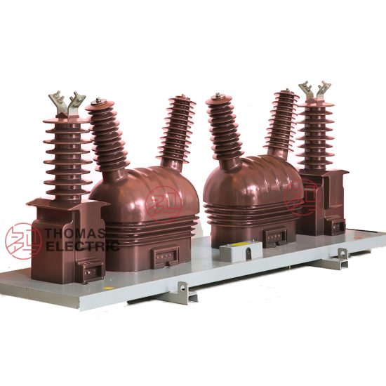
The SZW-35 is a single-phase, indoor/outdoor-rated cast-resin voltage transformer (VT) engineered for reliable operation in 10 kV distribution systems—designated as 11 kV under IEC 61869-3 nominal system voltage classification. This device provides galvanically isolated, scaled-down secondary voltages for accurate metering, revenue billing, and protective relay coordination in medium-voltage networks. Its construction leverages vacuum pressure impregnation (VPI) epoxy resin technology, ensuring superior dielectric integrity, environmental resilience, and long-term stability compared to traditional oil-filled alternatives.
Operating Principle of Cast-Resin Insulation
Cast-resin insulation in the SZW-35 employs a two-component cycloaliphatic epoxy resin system cured under vacuum and pressure. This process eliminates air voids and moisture ingress pathways, resulting in a homogeneous solid dielectric with high partial discharge inception voltage (>20 kV at 1.2 Ur). The primary and secondary windings are fully encapsulated within this resin matrix, which bonds directly to the GOES (grain-oriented electrical steel) core laminations. This monolithic structure prevents tracking, corona formation, and thermal degradation even under polluted or humid conditions. The dielectric strength exceeds 30 kV/mm, enabling compact design while maintaining safety margins per IEC 61869-3 clause 7.3. The absence of liquid insulation eliminates fire hazards, oil leakage risks, and maintenance associated with conservator tanks or breather systems.
Advantages Over Oil-Immersed Designs
Compared to oil-immersed VTs, the SZW-35 offers significant operational and safety benefits. It is inherently non-flammable (IEC 60695 glow-wire tested at 850°C), making it suitable for confined spaces like indoor switchrooms or urban substations where fire codes restrict combustible materials. The solid insulation exhibits negligible aging under thermal cycling (–40°C to +55°C ambient), with no need for periodic oil sampling or dielectric testing. Mechanical robustness is enhanced due to the rigid resin housing, which resists vibration from nearby circuit breakers or transformers. Additionally, the SZW-35 has a lower total cost of ownership: no oil disposal costs, reduced footprint, and immunity to oil expansion/contraction issues during temperature swings. Environmental compliance is simplified, as the unit contains no PCBs or hazardous liquids regulated under RoHS or REACH.
Typical Application Overview
The SZW-35 is deployed across diverse 10/11 kV infrastructure, including utility-owned primary substations, industrial plant switchyards, commercial building service entrances, and renewable energy interconnection points. In ring-main units (RMUs), it enables precise kWh metering for tariff billing while feeding overvoltage and undervoltage relays (e.g., ANSI 59/27 functions). For solar farms, it provides synchronized voltage signals to inverters and SCADA systems during grid-tied operation. Its compact dimensions (typically 380 mm height × 220 mm width) allow retrofitting into legacy panels originally designed for oil-filled VTs. The unit supports both single-phase and three-phase V-V or Y-Y configurations when used in sets, with standard secondary outputs of 100 V or 110 V for compatibility with global instrumentation.
Technical Specifications
The SZW-35 adheres strictly to IEC 61869-3 and GB/T 20840.3 requirements, with verified performance parameters validated through type tests at accredited laboratories. Below is a comprehensive specification table followed by environmental and operational constraints.
| Parameter | Value |
|---|---|
| System Voltage (IEC) | 11 kV |
| System Voltage (Domestic) | 10 kV |
| Rated Primary Voltage (Ur) | 11 / √3 kV (for phase-to-earth) |
| Rated Secondary Voltage | 100 V or 110 V (phase-to-phase); 100/√3 V or 110/√3 V (phase-to-neutral) |
| Voltage Ratio | (11,000 / √3) : (100 / √3) = 110:1 (standard) |
| Accuracy Class (Metering) | 0.2, 0.5 (per IEC 61869-3 Table 102) |
| Accuracy Class (Protection) | 3P, 6P (composite error ≤3% or ≤6% at 5× rated voltage) |
| Rated Output (Burden) | 10 VA, 15 VA, 30 VA, 50 VA (at cos φ = 0.8 lag) |
| Insulation Level (Um/IL) | 12 kV / 75 kV (1 min power frequency); 95 kV (LI BIL) |
| Partial Discharge | <10 pC at 1.2 × Ur (measured per IEC 60270) |
| Thermal Limit Output | ≥150% of rated output continuously without exceeding 50 K temperature rise |
| Core Material | GOES M4 grade, 0.3 mm thickness, step-lap joints |
| Resin System | Cycloaliphatic epoxy, VPI process, UL 94 V-0 rated |
Standard Service Conditions
The SZW-35 is rated for continuous operation under the following environmental conditions per IEC 60060-1 and GB/T 11022: ambient temperature range of –40°C to +55°C, relative humidity up to 95% (non-condensing), and installation altitude ≤1,000 m above sea level. For altitudes between 1,001 m and 3,000 m, the power frequency withstand voltage must be derated by 1% per 100 m above 1,000 m. The unit is designed for indoor use but can be deployed outdoors when equipped with an optional UV-resistant silicone rubber shed (IP54 rating). Pollution degree is classified as III per IEC 60664-1, suitable for industrial atmospheres with conductive dust or chemical vapors. No forced cooling is required; natural convection suffices for thermal management under 1.2× continuous overvoltage.
Electrical Performance Tolerances
Voltage ratio error must remain within ±0.2% for class 0.2 and ±0.5% for class 0.5 at 80–120% of rated primary voltage and 25–100% of rated burden. Phase displacement is limited to ±10 minutes for class 0.2 and ±30 minutes for class 0.5 under the same conditions. For protection accuracy class 3P, composite error shall not exceed 3% when subjected to 5× rated primary voltage at rated burden. Temperature rise limits are 50 K for windings (measured by resistance method) and 35 K for terminals, tested per IEC 61869-3 Annex C. Short-time thermal withstand capability is 1 s at 100× rated primary current (equivalent to system fault levels up to 25 kA).
Typical Applications
The SZW-35’s versatility stems from its dual certification (IEC and GB), robust construction, and precision metrology—making it ideal for critical infrastructure requiring decades of maintenance-free operation.
Substation Secondary Metering
In 10 kV primary substations, the SZW-35 supplies voltage inputs to multi-function meters (e.g., IEC 61850-7-4 compliant devices) for real-time monitoring of active/reactive energy, power factor, and harmonic distortion. Its class 0.2 accuracy ensures compliance with revenue metering regulations (e.g., EN 50470-3). When installed in parallel with current transformers, it enables vector group verification during commissioning. The low phase displacement minimizes errors in watt-hour calculations, especially under unbalanced load conditions common in mixed residential-commercial feeders. Utilities often deploy triple-SZW-35 sets in open-delta configuration to detect earth faults via residual voltage measurement.
Industrial Power Distribution
Within manufacturing facilities, the SZW-35 interfaces with motor protection relays (e.g., ANSI 46, 47) to prevent damage from phase imbalance or loss-of-voltage events. Its high thermal limit output (≥150% rated VA) accommodates transient burdens from multiple relays during startup sequences. In arc furnace plants or data centers with nonlinear loads, the GOES core’s low hysteresis loss maintains accuracy despite voltage waveform distortion up to 5% THD. The cast-resin housing resists chemical corrosion from airborne coolants or solvents, unlike oil-filled units that may degrade gaskets over time.
Renewable Energy Integration
Solar photovoltaic (PV) and wind farms utilize the SZW-35 for grid synchronization and anti-islanding protection. During low-voltage ride-through (LVRT) events, the VT must accurately track rapid voltage dips down to 15% of nominal for 150 ms—enabled by its fast magnetic response (<20 ms settling time). The 3P protection class ensures correct tripping of disconnect switches when islanding is detected. In microgrids, multiple SZW-35 units provide phase-locked loop (PLL) references for inverter control algorithms, with ratio stability maintained across –25°C to +50°C diurnal cycles.
Rural and Suburban Distribution Networks
For remote pole-mounted transformers or pad-mounted switchgear, the SZW-35’s maintenance-free design reduces outage risks in hard-to-access locations. Its lightweight (≈25 kg) simplifies aerial bucket installations, while the IP54 outdoor variant withstands monsoon rains or desert sandstorms. In regions with unstable grids (e.g., frequent voltage sags/swells), the wide operating range (80–120% Ur) prevents metering blackouts. Rural electrification projects in Southeast Asia and Africa commonly specify the SZW-35 due to its compatibility with both 100 V and 110 V secondary systems, accommodating legacy and modern instrumentation.
Compliance with International Standards
The SZW-35 is engineered to satisfy the most stringent global requirements for instrument voltage transformers, with explicit alignment to both IEC and Chinese national standards.
IEC 61869-3 Compliance Details
IEC 61869-3:2011 (“Instrument transformers – Part 3: Additional requirements for inductive voltage transformers”) governs all critical aspects of the SZW-35’s design. Key compliance areas include: insulation coordination (Clause 7), accuracy definitions (Clause 5), temperature rise limits (Clause 10), and short-circuit withstand (Clause 11). The unit undergoes full type testing per Annex A, including power frequency withstand (75 kV for 1 min), lightning impulse (95 kV peak, 1.2/50 μs wave), and partial discharge measurement. Accuracy verification follows Clause 6 procedures using calibrated reference standards traceable to NIST or PTB. Marking includes IEC-required data: manufacturer ID, serial number, Ur, ratio, accuracy class, and year of manufacture.
GB/T 20840.3 Alignment
GB/T 20840.3-2013 (“Instrument transformers – Part 3: Additional requirements for inductive voltage transformers”) mirrors IEC 61869-3 but adds China-specific provisions. Notably, GB requires a minimum creepage distance of 240 mm/kV for pollution degree IV (vs. IEC’s 20 mm/kV for degree III), addressed in the SZW-35 via extended silicone sheds. Thermal stability tests mandate 4-hour continuous operation at 1.5× rated output—exceeding IEC’s 1.2× requirement. Burden designation uses “VA” instead of “Ω,” and secondary voltage options include 100/3 V for residual winding applications. All SZW-35 units sold in China carry CMA/CNAS certification marks from authorized test labs like CETC or SGS Shanghai.
Key Differences Between IEC and Domestic Standards
While IEC 61869-3 focuses on functional interoperability, GB/T 20840.3 emphasizes environmental durability for China’s diverse climates—from humid Guangdong to arid Xinjiang. GB mandates salt fog testing (ASTM B117, 96 hours) for coastal installations, whereas IEC defers to user-specified pollution classes. Accuracy class notation differs slightly: IEC uses “0.2” while GB may list “0.2级.” Crucially, GB requires factory acceptance tests (FAT) for every unit, including ratio and polarity checks, whereas IEC permits sample testing for batches ≤50 units. Despite these nuances, the SZW-35’s dual-certified design ensures seamless deployment in multinational projects.
On-Site Testing Procedures
Post-installation verification is essential to confirm the SZW-35’s integrity and calibration. All tests should follow IEC 60060-2 and IEEE C57.13 guidelines.
Insulation Resistance Test
Using a 2,500 V DC megohmmeter, measure insulation resistance between primary winding and ground, secondary winding and ground, and primary-to-secondary. Acceptance criteria: ≥1,000 MΩ at 20°C ambient. Correct for temperature using the formula RT2 = RT1 × 2((T1–T2)/10). Values below 500 MΩ indicate moisture ingress or resin cracking and require drying or replacement. Perform before and after power frequency withstand tests to detect insulation degradation.
Turns Ratio Test
Apply a low-voltage AC source (50–100 V) to the primary and measure secondary voltage with a calibrated true-RMS meter. Calculate ratio as Vpri/Vsec. Tolerance: ±0.2% for class 0.2, ±0.5% for class 0.5. Use a dedicated ratio tester (e.g., Omicron CT Analyzer) for automated comparison against nameplate values. Deviations >1% suggest turn-to-turn shorts or winding deformation from shipping shock.
Polarity Test
Verify reducing polarity per IEC 61869-3 Figure 101. Connect a 6–12 V battery across primary terminals (H1+, H2–) and observe secondary voltage polarity with a DC voltmeter (X1+, X2–). A momentary positive deflection confirms correct dot convention. Incorrect polarity causes 180° phase shift, leading to erroneous wattmeter readings or relay misoperation. Repeat three times to eliminate contact bounce artifacts.
Power Frequency Withstand Voltage Test
Apply 75 kV RMS at 50 Hz between primary and grounded secondary/core for 1 minute. Ramp voltage at 2 kV/s to avoid transient overstress. Monitor for flashover, excessive leakage current (>1 mA), or audible discharge. Post-test insulation resistance must not drop >30% from pre-test value. For field testing, use a portable resonant frequency generator to minimize input power requirements.
Open-Circuit Characteristic Test
With secondary open, gradually increase primary voltage from 10% to 120% of Ur while recording excitation current. Plot Iexc vs. Vpri; the knee point should occur ≥110% Ur. Excessive magnetizing current (>5% of rated primary current at 100% Ur) indicates core saturation due to mechanical stress or poor lamination stacking. Compare results to factory baseline curves—deviations >10% warrant core inspection.
Preventive Maintenance Guide
Although cast-resin VTs require minimal upkeep, scheduled inspections extend service life and prevent unexpected failures.
Periodic Inspection Protocol
Conduct annual visual checks for: surface cracks in resin housing, terminal corrosion, loose mounting bolts, and contamination buildup (dust, salt, bird droppings). Clean with deionized water and soft brush—never abrasive cleaners. Verify torque on M10 primary terminals (25 N·m) and M6 secondary terminals (8 N·m). Use infrared thermography during peak load to detect hot spots (>10 K above ambient at connections). Record partial discharge levels if online PD sensors are installed; values >20 pC trigger detailed diagnostics.
Maintenance Intervals and Fault Diagnosis
Every five years, perform insulation resistance, ratio, and polarity tests regardless of operational history. Replace units exhibiting: ratio error drift >0.3% per year, insulation resistance decline >20% annually, or visible UV degradation (chalking) on outdoor models. Common failure modes include: (1) terminal overheating from undersized cables—check conductor ampacity per IEC 60364; (2) resonance-induced overvoltage from improper grounding—ensure secondary neutral is solidly earthed per IEC 61869-3 Clause 8.4; (3) ferroresonance in unearthed systems—install damping resistors across open delta secondaries. Maintain a logbook with test results, environmental conditions, and corrective actions.
| Interval | Task | Acceptance Criteria |
|---|---|---|
| Annual | Visual inspection, IR scan | No cracks, temp rise ≤10 K |
| 5 Years | Insulation resistance, ratio test | R ≥1,000 MΩ; ratio error within class |
| 10 Years | Full electrical retest (incl. PD) | PD <15 pC at 1.2 Ur |
| After Fault | Post-fault diagnostics | No change in baseline parameters |
Conclusion
The SZW-35 11kV cast-resin voltage transformer represents a benchmark in reliability, accuracy, and compliance for modern medium-voltage networks. By leveraging advanced VPI epoxy resin encapsulation and GOES core technology, it eliminates the fire, environmental, and maintenance liabilities inherent in oil-immersed designs while delivering metrological precision demanded by revenue-grade metering and critical protection schemes. Its dual adherence to IEC 61869-3 and GB/T 20840.3 ensures global deployability—from European smart grids to Chinese rural electrification projects—with consistent performance across extreme temperatures, humidity, and pollution levels. Rigorous factory and field testing protocols guarantee long-term stability, with expected service life exceeding 25–30 years under standard operating conditions. For engineers specifying instrumentation in 10 kV (11 kV IEC) systems, the SZW-35 offers a future-proof solution that balances technical excellence with lifecycle cost efficiency. Its robust design withstands the electrical, thermal, and mechanical stresses of contemporary distribution networks, making it an indispensable component for safe, accurate, and resilient power delivery infrastructure.