Article Content
11kV Cast-Resin Voltage Transformer SZV-10K for Metering and Protection – IEC 61869-3 Standard
Introduction to the SZV-10K Voltage Transformer
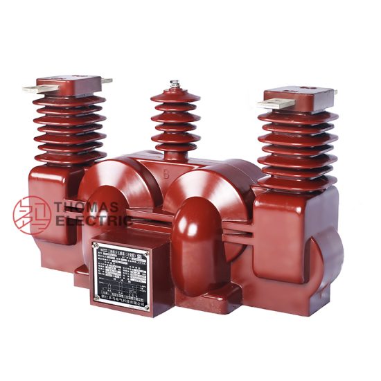
The SZV-10K is a single-phase, electromagnetic voltage transformer (VT) engineered for reliable operation in medium-voltage distribution networks rated at 10 kV system voltage, corresponding to an IEC-standard primary voltage of 11 kV. Designed with vacuum pressure impregnated (VPI) epoxy resin insulation, this device transforms high primary voltages to standardized secondary levels—typically 100 V or 110 V—for safe interfacing with metering instruments, protective relays, and monitoring systems. Its robust construction ensures long-term stability under electrical, thermal, and environmental stress, making it suitable for both indoor switchgear and outdoor substation applications.
Operating Principle of Cast-Resin Insulation
Cast-resin insulation in the SZV-10K employs a vacuum pressure impregnation (VPI) process where high-purity epoxy resin fully encapsulates the primary and secondary windings around a grain-oriented electrical steel (GOES) core. This eliminates air voids and moisture ingress pathways, significantly enhancing dielectric strength and partial discharge resistance. The resin matrix provides mechanical rigidity, thermal conductivity for heat dissipation, and resistance to tracking and erosion under polluted conditions. Unlike oil-filled designs, the solid insulation system requires no maintenance related to fluid levels or degradation, and it eliminates fire hazards associated with flammable insulating media. The homogeneous dielectric structure ensures uniform electric field distribution, critical for maintaining accuracy class performance across the operating range.
Advantages Over Oil-Immersed Designs
Compared to traditional oil-immersed voltage transformers, the SZV-10K offers distinct technical and operational benefits. First, its dry-type construction eliminates risks of oil leakage, environmental contamination, and fire propagation—critical in urban substations or confined indoor spaces. Second, the absence of oil simplifies transportation, handling, and disposal logistics, reducing lifecycle costs. Third, the epoxy resin’s superior thermal stability allows consistent performance across ambient temperatures from –25°C to +40°C without derating. Additionally, the compact physical footprint enables integration into space-constrained switchgear panels. From a reliability standpoint, cast-resin VTs exhibit lower failure rates due to immunity to oil oxidation, moisture absorption, and gas formation under partial discharge activity. These attributes make the SZV-10K particularly suited for modern smart grids demanding minimal maintenance and high availability.
Typical Application Overview
The SZV-10K is deployed across diverse power infrastructure segments where accurate voltage transformation is essential for measurement fidelity and protection coordination. Primary use cases include utility-owned 10 kV/11 kV distribution substations, industrial plant power centers, renewable energy interconnection points (e.g., solar farms with 10 kV collector systems), and rural electrification networks. In these environments, the VT supplies secondary voltage signals to revenue-class kWh meters, digital protective relays (e.g., overvoltage, undervoltage, directional elements), power quality analyzers, and SCADA remote terminal units (RTUs). Its compliance with IEC 61869-3 ensures interoperability with international instrumentation standards, while adherence to GB/T 20840.3 facilitates deployment in domestic Chinese grid applications.
Technical Specifications
The SZV-10K voltage transformer is engineered to meet stringent electrical and environmental performance criteria as defined by IEC 61869-3 and GB/T 20840.3. Below are the detailed technical parameters governing its design, operation, and testing.
Rated Electrical Parameters
The primary rated voltage is 11 kV (IEC standard), corresponding to a 10 kV nominal system voltage. Standard secondary outputs include 100 V or 110 V (line-to-neutral), with optional dual secondary windings for simultaneous metering and protection functions. Accuracy classes are available per IEC 61869-3: Class 0.2 or 0.5 for metering, and Class 3P or 6P for protection applications. Rated burden ranges from 10 VA to 100 VA per winding, with thermal short-time current rating of 1 second at 100 A (for fault current withstand during system transients). The insulation level complies with IEC 60071-1: LI 75 kV (lightning impulse) and AC 28 kV rms (power frequency withstand for 1 minute). Phase displacement is maintained within ±10 minutes for Class 0.2 and ±30 minutes for Class 0.5 at rated load and power factor of 0.8 lagging.
Environmental and Service Conditions
The SZV-10K is rated for operation under standard service conditions per IEC 60060-1: ambient temperature range of –25°C to +40°C, relative humidity up to 95% non-condensing, and installation altitude not exceeding 1,000 meters above sea level. For altitudes between 1,000 m and 2,000 m, a derating factor of 1.0% per 100 m applies to the power frequency withstand voltage. The device is suitable for both indoor and outdoor installation when housed in appropriate enclosures; outdoor versions feature UV-stabilized resin and hydrophobic surface properties to resist pollution layer formation. The maximum permissible continuous overvoltage is 1.2 × Un (13.2 kV) for 8 hours, and 1.5 × Un (16.5 kV) for 30 seconds during transient events.
Construction and Materials
The magnetic core is fabricated from high-permeability grain-oriented electrical steel (GOES) laminations, annealed to minimize hysteresis losses and ensure low excitation current—critical for maintaining ratio error within tolerance under light-load conditions. Windings are wound with oxygen-free copper conductors, insulated with Class F (155°C) enamel, and fully embedded in cycloaliphatic epoxy resin via VPI. Terminal connections utilize tinned copper studs with M10 threads for primary and screw-type terminals for secondary circuits, rated for 600 V insulation. The housing includes integrated mounting brackets and creepage-extending sheds for outdoor use, achieving a minimum creepage distance of 25 mm/kV in accordance with IEC 60815 pollution severity class II.
Typical Applications
The SZV-10K serves as a foundational component in modern power systems requiring precise, reliable voltage transformation for secondary systems. Its versatility spans multiple sectors and grid architectures.
Substation Secondary Metering
In 10 kV/11 kV distribution substations, the SZV-10K provides the reference voltage signal for revenue metering and energy management systems. Connected to kWh meters compliant with IEC 62053-22, it ensures billing accuracy within ±0.2% for Class 0.2 configurations. The VT’s low phase displacement minimizes errors in reactive energy measurement, crucial for power factor correction schemes. In digital substations, the secondary output feeds merging units (MUs) that digitize analog signals for IEC 61850-9-2 LE sampled value transmission. The cast-resin design’s immunity to vibration and thermal cycling ensures long-term calibration stability, reducing the need for frequent recalibration compared to oil-filled alternatives.
Industrial Power Distribution
Within heavy industrial facilities—such as steel mills, chemical plants, and data centers—the SZV-10K integrates into 10 kV switchgear to support motor protection relays, arc-flash detection systems, and power quality monitors. Its high short-time thermal withstand capability allows survival during downstream fault conditions without saturation or damage. The compact form factor enables retrofitting into legacy switchgear panels where space constraints preclude oil-filled units. Furthermore, the absence of flammable materials aligns with stringent industrial safety codes (e.g., NFPA 70E), particularly in hazardous locations.
Renewable Energy Integration
Solar photovoltaic (PV) and wind farms frequently employ 10 kV collector systems to aggregate generation before step-up transformation. At the point of interconnection (POI), the SZV-10K supplies voltage signals to anti-islanding relays, synchrophasor measurement units (PMUs), and SCADA systems for grid compliance monitoring per IEEE 1547 or GB/T 19964. Its fast transient response and low harmonic distortion ensure accurate detection of voltage sags, swells, and islanding events. The outdoor-rated version withstands desert, coastal, or alpine environments common in renewable sites, with resin formulations resistant to salt fog, sand abrasion, and UV degradation.
Rural and Suburban Distribution Networks
In rural electrification projects and suburban ring-main units (RMUs), the SZV-10K enables cost-effective voltage monitoring and protection without the logistical burden of oil handling. Mounted on pole-top platforms or pad-mounted switchgear, it supports single-phase or three-phase VT banks for ground-fault detection in ungrounded or high-resistance grounded systems. The 25–30 year service life reduces total cost of ownership in remote areas where maintenance access is limited. Its standardized secondary output simplifies spare parts inventory and technician training across utility fleets.
Compliance with International Standards
The SZV-10K is certified to meet the rigorous requirements of global and regional standards governing instrument transformers, ensuring interoperability, safety, and performance consistency.
IEC 61869-3 Compliance Details
IEC 61869-3 specifies performance, testing, and marking requirements for inductive voltage transformers. The SZV-10K complies fully with clauses covering rated values, accuracy limits, temperature rise, short-circuit withstand, and insulation coordination. Key verified parameters include ratio error ≤ ±0.2% and phase displacement ≤ ±10′ for Class 0.2 at 25–100% of rated burden. Temperature rise tests confirm winding limits of ≤ 60 K above ambient under continuous rated load. Partial discharge measurements are ≤ 10 pC at 1.2 × Um/√3 (where Um = 12 kV), well below the 20 pC threshold for cast-resin devices. All units undergo routine tests per Clause 10, including power frequency withstand, turns ratio verification, and polarity checks.
GB/T 20840.3 Alignment
For deployment in China, the SZV-10K aligns with GB/T 20840.3—equivalent to IEC 61869-3 but with minor national deviations. Notably, GB/T permits a slightly higher phase displacement tolerance (±15′ for Class 0.2) and specifies 100 V as the default secondary voltage (vs. 100/√3 V in some IEC contexts). The insulation coordination follows GB 311.1, which adopts identical LI 75 kV and AC 28 kV test levels. Marking requirements include Chinese labeling of terminals (A, X for primary; a, x for secondary) and inclusion of the China Compulsory Certification (CCC) mark. Factory test reports are issued in bilingual format to satisfy both domestic grid operators and international EPC contractors.
Key Differences Between IEC and Domestic Standards
While IEC 61869-3 and GB/T 20840.3 are harmonized, practical differences affect procurement and commissioning. IEC emphasizes global interoperability with flexible secondary voltages (100 V, 110 V, 115 V), whereas GB/T standardizes on 100 V for new installations. Environmental testing under IEC includes optional cold climate validation (–40°C), while GB/T focuses on high-humidity and high-altitude scenarios relevant to southwestern China. Certification pathways also differ: IEC compliance is self-declared with third-party witness testing, whereas GB/T mandates full type testing at accredited Chinese laboratories (e.g., CESI China). Engineers must verify local grid code requirements to select the appropriate certification package.
On-Site Testing Procedures
Post-installation verification ensures the SZV-10K performs within specified tolerances and maintains system integrity. The following tests are mandatory per IEC 61869-3 Clause 11 and utility commissioning protocols.
Insulation Resistance Test
Using a 2,500 V DC megohmmeter, measure insulation resistance between primary winding and ground, secondary winding and ground, and between windings. Acceptance criteria: ≥ 1,000 MΩ at 20°C. Correct for temperature using RT2 = RT1 × 2(T1–T2)/10. Low readings indicate moisture ingress or resin cracking—requiring drying or replacement. Perform before and after power frequency withstand tests to detect insulation degradation.
Turns Ratio Test
Apply a low-voltage AC source (50–100 V) to the primary and measure secondary voltage with a calibrated true-RMS meter. Calculate actual ratio = Vp/Vs. Tolerance: ±0.2% for Class 0.2, ±0.5% for Class 0.5. Use a dedicated ratio bridge (e.g., Omicron CT Analyzer) for highest accuracy. Deviations beyond tolerance suggest winding shorts or incorrect tap selection.
Polarity Test
Verify reducing polarity per IEC 61869-3 Figure 3. Connect a 6–12 V battery momentarily between A (+) and X (–) on primary. Observe secondary voltmeter connected between a (+) and x (–): a momentary positive deflection confirms correct polarity. Incorrect polarity causes 180° phase reversal, leading to relay misoperation or metering errors in polyphase systems.
Power Frequency Withstand Voltage Test
Apply 28 kV rms at 50 Hz between primary and ground (secondary shorted and grounded) for 1 minute. Use a calibrated test transformer with overcurrent trip set at 1.5 × expected capacitive current. No flashover or disruptive discharge constitutes pass. Reduce voltage gradually post-test to avoid resonant overvoltages. This validates insulation integrity after transport and installation stresses.
Open-Circuit Characteristic Test
With secondary open, apply 10–120% of rated primary voltage in 10% increments. Record excitation current and secondary voltage. Plot Vs vs. Iexc to identify core saturation onset (typically >120% Un). Excessive excitation current at rated voltage indicates core lamination damage or shorted turns. This test is critical for VTs used in ferroresonance-prone networks.
Preventive Maintenance Guide
Although cast-resin VTs require minimal maintenance, periodic inspection extends service life and prevents unexpected failures in critical applications.
Annual Visual and Electrical Inspection
Inspect for surface cracks, tracking marks, or discoloration on the resin housing—indicative of partial discharge or UV degradation. Clean sheds with deionized water if pollution accumulation exceeds 0.1 mg/cm² equivalent salt deposit density (ESDD). Verify terminal tightness (torque: 15 N·m for M10 studs) and check for corrosion on secondary terminals. Perform insulation resistance and turns ratio tests annually to establish baseline trends. Sudden drops in insulation resistance (>50% from baseline) warrant further investigation.
Five-Year Comprehensive Maintenance
Every five years, conduct partial discharge measurement using IEC 60270 methodology at 1.1 × Un/√3. Acceptable level: ≤ 15 pC. Re-measure open-circuit characteristics to detect core aging. Inspect mounting hardware for fatigue or loosening due to thermal cycling. Replace gaskets on outdoor terminal boxes if hardened or cracked. Update maintenance logs with all test data for lifecycle asset management. Units showing progressive degradation should be scheduled for replacement within 2–3 years.
Maintenance Intervals and Fault Diagnosis
| Interval | Activity | Acceptance Criteria |
|---|---|---|
| Annual | Visual inspection, IR test, ratio check | IR ≥ 1,000 MΩ; ratio error within class limits |
| 5 Years | Partial discharge test, open-circuit curve | PD ≤ 15 pC; no shift in knee point |
| Event-Based | After system fault or lightning strike | Repeat all routine tests; compare to baseline |
Common faults include secondary winding opens (detected by infinite IR), core saturation (high excitation current), and terminal corrosion (increased contact resistance). Never attempt internal repair—replace the unit if internal defects are suspected.
Conclusion
The SZV-10K 11kV cast-resin voltage transformer represents a technically mature solution for medium-voltage metering and protection applications, combining the dielectric reliability of epoxy resin insulation with the magnetic efficiency of GOES cores. Its compliance with IEC 61869-3 and GB/T 20840.3 ensures global acceptance and seamless integration into diverse grid architectures—from urban substations to remote renewable sites. Key advantages over legacy oil-filled designs include zero fire risk, minimal maintenance, compact size, and immunity to environmental contaminants. Rigorous factory and field testing protocols guarantee performance within tight accuracy tolerances (±0.2% ratio error, ±10′ phase displacement) across the full operating range. With a design life of 25–30 years under standard service conditions, the SZV-10K delivers exceptional lifecycle value while supporting the accuracy demands of modern digital protection and revenue metering systems. Its robust construction and standardized interfaces make it a dependable choice for engineers prioritizing safety, longevity, and regulatory compliance in 10 kV/11 kV distribution networks.
Q1: Can the SZV-10K be used in a 12 kV system?
No. The SZV-10K is rated for 11 kV maximum system voltage (Um = 12 kV per IEC 60038). Continuous operation above 11 kV violates insulation coordination and voids certification. For 12 kV systems, select a VT rated for Um = 17.5 kV (e.g., 15 kV class).
Q2: What is the maximum altitude rating without derating?
1,000 meters above sea level. Above this, reduce power frequency withstand voltage by 1% per 100 m increment up to 2,000 m. Beyond 2,000 m, consult the manufacturer for special design.
Q3: Is the SZV-10K suitable for ferroresonance-prone networks?
Yes, but only with proper damping. Use a resistive burden ≥ 25% of rated VA on all secondaries, or install a dedicated ferroresonance suppression circuit per IEC TR 61869-102.
Q4: Can I parallel two SZV-10K units for increased burden capacity?
No. Voltage transformers must never be paralleled due to circulating currents caused by minute ratio or phase errors. Use a single unit with adequate rated output instead.
Q5: What secondary voltage options are available?
Standard options: 100 V, 100/√3 V, 110 V, or 110/√3 V. Dual secondary configurations (e.g., 0.2/3P) are available for combined metering and protection.