Article Content
11kV Cast-Resin Voltage Transformer VT-10K for Metering and Protection – IEC 61869-3 Standard
Introduction to the VT-10K Voltage Transformer
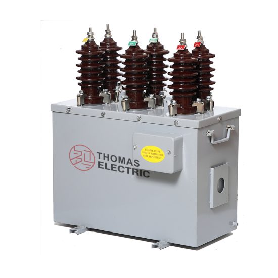
The VT-10K is a precision-engineered cast-resin voltage transformer (VT) designed for reliable operation in 11 kV (IEC-rated) or 10 kV (domestic system nominal) medium-voltage distribution networks. As a critical interface between primary high-voltage circuits and secondary instrumentation, it provides galvanic isolation while accurately scaling down system voltage to standardized secondary levels—typically 100 V or 110 V—for use in metering, protective relaying, and control systems. Its construction leverages vacuum pressure impregnation (VPI) epoxy resin technology, ensuring superior dielectric strength, mechanical robustness, and environmental resilience compared to traditional oil-immersed alternatives.
Operating Principle and Cast-Resin Insulation Technology
Voltage transformers operate on the principle of electromagnetic induction, where a primary winding connected across the line-to-ground or line-to-line voltage induces a proportional voltage in a secondary winding through a magnetic core. In the VT-10K, the core is fabricated from grain-oriented electrical steel (GOES), which minimizes hysteresis and eddy current losses, thereby enhancing accuracy under both steady-state and transient conditions. The entire active assembly—windings and core—is fully encapsulated in a flame-retardant, halogen-free epoxy resin matrix via the VPI process. This technique eliminates air voids, prevents moisture ingress, and provides uniform thermal conductivity, resulting in excellent partial discharge performance (<5 pC at 1.2 × Um/√3). Unlike oil-filled units, the VT-10K requires no maintenance related to fluid levels or gas monitoring, making it ideal for indoor substations, urban switchgear, and environments with fire safety constraints.
Advantages Over Oil-Immersed Designs
The shift toward cast-resin insulation in modern VTs like the VT-10K addresses several limitations inherent in oil-immersed counterparts. First, the solid dielectric eliminates risks of leakage, flammability, and environmental contamination—critical considerations in confined or public-access installations. Second, the monolithic resin structure offers superior mechanical stability against seismic loads and short-circuit forces, withstanding dynamic stresses up to 0.5g without degradation. Third, thermal performance is enhanced: the epoxy resin’s thermal conductivity (~0.8 W/m·K) facilitates efficient heat dissipation, enabling continuous operation at ambient temperatures up to +40°C without derating. Finally, the compact footprint and lighter weight (typically 35–45 kg) simplify handling, mounting, and integration into ring main units (RMUs) or metal-enclosed switchgear. These attributes collectively reduce lifecycle costs and improve operational safety, aligning with global trends toward dry-type instrument transformers in distribution networks.
Typical Deployment Scenarios
The VT-10K is commonly deployed in utility-owned or industrial 10/11 kV distribution substations where accurate voltage measurement and fast fault detection are essential. It interfaces directly with revenue-class energy meters (Class 0.2 or 0.5S per IEC 62053), distance relays, overvoltage/undervoltage protection schemes, and power quality analyzers. Its dual-winding configuration supports simultaneous connection to metering and protection burdens, with isolated secondary terminals preventing cross-interference. Applications span urban underground networks, commercial complexes, manufacturing plants, and renewable energy interconnection points (e.g., solar farms feeding into 11 kV grids). The unit’s IP54-rated enclosure ensures reliable outdoor performance in coastal or dusty regions, while its low temperature rise (<60 K above ambient) guarantees stable ratio and phase error characteristics across seasonal variations.
Technical Specifications
The VT-10K adheres to stringent electrical and mechanical parameters defined by IEC 61869-3 and GB/T 20840.3, ensuring interoperability and long-term reliability in diverse grid environments.
| Parameter | Value |
|---|---|
| System Voltage (Un) | 10 kV (domestic nominal) |
| IEC Rated Voltage (Um) | 11 kV |
| Primary Voltage Configuration | 11,000 / √3 V (line-to-ground) |
| Secondary Voltage | 100 V or 110 V (line-to-neutral) |
| Rated Voltage Ratio | 11,000/√3 : 100/√3 V or 11,000/√3 : 110/√3 V |
| Accuracy Class (Metering) | 0.2, 0.5 |
| Accuracy Class (Protection) | 3P, 6P |
| Rated Output (per winding) | 30 VA, 50 VA, or 100 VA (user-selectable) |
| Insulation Level (LI/AC) | 75 kV / 28 kV (1 min, 50 Hz) |
| Short-Time Thermal Withstand | 1 s at 16 kA (symmetrical) |
| Ambient Temperature Range | –25°C to +40°C |
| Altitude Limit | ≤ 1,000 m (derating required above) |
| Relative Humidity | Up to 95% non-condensing |
| Core Material | Grain-Oriented Electrical Steel (GOES), M4 grade |
| Insulation System | VPI Epoxy Resin, UL 94 V-0 rated |
| Partial Discharge Level | <5 pC at 1.2 × Um/√3 |
| Phase Error (Class 0.2) | ≤ ±10 minutes |
| Voltage Error (Class 0.2) | ≤ ±0.2% |
Electrical Performance Characteristics
The VT-10K delivers high-fidelity voltage transformation across its specified burden range. For metering applications, Class 0.2 accuracy ensures voltage error within ±0.2% and phase displacement not exceeding ±10 minutes at 25–100% of rated burden. Protection windings (Class 3P/6P) maintain ratio error within ±3% or ±6%, respectively, even under fault-induced saturation conditions up to 2× rated voltage. The transformer exhibits low magnetizing current (<0.5% of rated primary current), minimizing loading effects on the primary circuit. Frequency response remains linear from 48 Hz to 52 Hz, accommodating grid frequency deviations without compromising measurement integrity. Secondary terminals are clearly labeled (a-n for metering, da-dn for protection) and housed in an insulated terminal box with IP2X finger-safe protection.
Environmental and Mechanical Ratings
Designed for both indoor and outdoor service, the VT-10K features a UV-stabilized epoxy housing resistant to tracking and erosion. The creepage distance exceeds 25 mm/kV (medium pollution class III per IEC 60815), ensuring flashover resistance in humid or saline atmospheres. Mounting is achieved via standard M12 threaded inserts compatible with DIN 42600 brackets. The unit weighs approximately 40 kg and measures 320 mm (H) × 220 mm (W) × 180 mm (D), facilitating retrofit into existing switchgear bays. No external breather or conservator is required, eliminating maintenance associated with desiccant replacement or oil sampling. Thermal design ensures temperature rise remains below 60 K above ambient at full load, preserving insulation life expectancy beyond 30 years under normal operating conditions.
Typical Applications
The VT-10K serves as a foundational component in modern medium-voltage infrastructure, enabling precise monitoring and rapid fault response across diverse sectors.
Substation Secondary Metering Systems
In utility-owned 11 kV distribution substations, the VT-10K supplies scaled voltage signals to revenue metering panels compliant with IEC 62053-22. Its Class 0.2 accuracy ensures billing-grade measurements, while low phase error minimizes reactive energy miscalculation. The transformer often operates in parallel with CTs to feed three-phase kWh meters, demand recorders, and SCADA RTUs. For example, in a European DSO’s urban substation, VT-10K units provide 100 V secondary outputs to AMR-enabled meters, enabling remote load profiling and tamper detection. The cast-resin design eliminates oil-related fire hazards in confined indoor rooms, satisfying EN 50171 safety mandates.
Industrial Power Distribution Networks
Large manufacturing facilities—such as automotive plants or data centers—use the VT-10K to monitor incoming 10 kV feeders for power quality and protection coordination. Here, the dual secondary windings allow one output to drive digital multifunction meters (e.g., for harmonics analysis) while the other feeds overvoltage relays (e.g., ANSI 59). The transformer’s high saturation margin (>2.5× Un) prevents distortion during motor-start transients or capacitor bank switching. In a recent semiconductor fab installation, VT-10K units enabled sub-cycle voltage sag detection, triggering UPS transfers within 4 ms to protect sensitive lithography tools.
Renewable Energy Integration Points
Solar photovoltaic (PV) farms and wind parks frequently connect to 11 kV collector grids, requiring accurate voltage sensing for anti-islanding protection and grid code compliance (e.g., ENTSO-E requirements). The VT-10K’s fast response time (<20 ms) and low remanence ensure reliable detection of islanding events. Its robust insulation withstands frequent switching transients from inverters, while the dry-type construction avoids environmental concerns in agricultural or ecologically sensitive zones. A 20 MW solar project in Spain deployed VT-10K units at each inverter sub-array, feeding synchrophasor measurements to a central controller for real-time grid support functions.
Rural and Suburban Distribution Feeders
In remote or lightly loaded networks, the VT-10K enables cost-effective voltage regulation and fault location. Mounted on pole-top reclosers or pad-mounted switchgear, it provides inputs to voltage regulators and sectionalizers. The unit’s wide ambient tolerance (–25°C to +40°C) ensures operation in alpine or desert climates without heater or cooler add-ons. In a rural electrification program in Southeast Asia, VT-10K transformers were integrated into smart RMUs, allowing utilities to remotely monitor feeder voltage profiles and optimize tap settings to maintain customer-end voltage within ±5% of nominal.
Compliance with International Standards
The VT-10K is engineered to meet the rigorous requirements of both international and domestic regulatory frameworks, ensuring global deployability and interoperability.
IEC 61869-3 Certification Details
As a dedicated voltage transformer, the VT-10K complies fully with IEC 61869-3:2011 (“Instrument transformers – Part 3: Additional requirements for inductive voltage transformers”). This standard governs accuracy classes, insulation coordination, temperature rise limits, and type tests. Key conformity aspects include: (1) verification of voltage and phase errors across 25–100% burden at rated frequency; (2) power-frequency withstand test at 28 kV for 1 minute; (3) lightning impulse test at 75 kV (1.2/50 µs wave); and (4) partial discharge measurement per IEC 60270. All production units undergo routine tests including ratio verification (±0.1% tolerance), polarity check, and insulation resistance (>1,000 MΩ at 2,500 V DC). Type test reports are available upon request, demonstrating compliance with all normative clauses.
Alignment with GB/T 20840.3
For Chinese domestic markets, the VT-10K meets GB/T 20840.3-2013, which largely harmonizes with IEC 61869-3 but includes localized requirements. Notably, GB/T specifies a minimum short-circuit withstand of 16 kA for 1 s (vs. IEC’s performance-based approach) and mandates creepage distances ≥20 mm/kV for light-pollution areas. The VT-10K exceeds these thresholds with 25 mm/kV and 16 kA rating. Additionally, GB/T requires thermal stability testing at 1.1× Un for 8 hours—successfully passed by the VT-10K with temperature rise stabilized at 58 K. Dual certification allows seamless deployment in Belt and Road Initiative projects requiring both IEC and Chinese standards.
Key Differences Between IEC and Domestic Requirements
While IEC 61869-3 emphasizes performance-based criteria (e.g., error limits under defined burdens), GB/T 20840.3 often prescribes fixed test parameters. For instance, IEC permits user-defined accuracy combinations (e.g., 0.2/3P), whereas GB/T historically favored separate metering/protection units—though recent revisions now accept multi-winding designs. Another distinction lies in altitude correction: IEC applies a linear derating factor above 1,000 m, while GB/T uses stepped reductions at 2,000 m and 3,000 m. The VT-10K’s design incorporates conservative insulation margins, ensuring compliance in both regimes without modification.
On-Site Testing Procedures
Post-installation verification is critical to ensure the VT-10K performs within specification. The following tests should be conducted before energizing the primary circuit.
Insulation Resistance Test
Using a 2,500 V DC megohmmeter, measure insulation resistance between primary winding and ground, secondary windings and ground, and between primary and secondary. Acceptance criterion: ≥1,000 MΩ at 20°C. Correct for temperature using RT2 = RT1 × 2(T1–T2)/10. Low readings may indicate moisture ingress or resin cracking—requiring drying or replacement. This test validates the integrity of the cast-resin barrier and terminal seals.
Turns Ratio Verification
Apply a low-voltage AC signal (50–100 V) to the primary and measure secondary voltage with a calibrated voltmeter. Calculate actual ratio and compare to nameplate. Tolerance: ±0.1% for Class 0.2, ±0.2% for Class 0.5. Modern ratio testers (e.g., Omicron CT Analyzer) automate this with <0.01% uncertainty. Deviations beyond tolerance suggest winding shorts or incorrect tap selection.
Polarity Confirmation
Connect a 6–12 V DC source momentarily across the primary (H1 to H2). Observe secondary voltage polarity with a DC voltmeter (X1 to X2). A positive deflection confirms subtractive (reducing) polarity—standard for IEC VTs. Incorrect polarity reverses phase angle, causing metering errors or relay misoperation. This test is mandatory when integrating with directional overcurrent or distance protection.
Power Frequency Withstand Test
Apply 28 kV RMS at 50 Hz between primary and ground (with secondaries shorted and grounded) for 1 minute. Monitor for flashover, excessive leakage current (>1 mA), or audible discharge. This verifies basic insulation level (BIL) compliance. Use a calibrated test transformer with overcurrent trip set at 100 mA. Never perform this test if moisture is suspected.
Open-Circuit Characteristic Test
Gradually increase primary voltage from 0 to 120% Un while measuring secondary voltage and excitation current. Plot Vsec vs. Imag. The knee point should exceed 150% Un, confirming adequate saturation margin for protection applications. Excessive magnetizing current at rated voltage indicates core defects or shorted turns. This test is particularly valuable after transport or seismic events.
Preventive Maintenance Guide
Although cast-resin VTs require minimal maintenance, periodic checks extend service life and prevent unexpected failures.
Annual Visual and Functional Inspection
Inspect for surface cracks, tracking marks, or discoloration on the resin housing. Verify terminal tightness (torque: 15 N·m for M6 screws) and absence of corrosion. Check secondary wiring for insulation damage or loose connections. Perform insulation resistance and ratio tests annually in critical applications (e.g., revenue metering). Record results in a logbook to track degradation trends. Any crack deeper than 2 mm warrants immediate replacement due to potential partial discharge escalation.
Five-Year Comprehensive Assessment
Every 60 months, conduct a full suite of tests: open-circuit characteristic, partial discharge (if portable PD detector available), and thermal imaging under load. Compare results against baseline commissioning data. A >20% increase in magnetizing current or PD level >10 pC indicates internal aging. Also inspect mounting hardware for fatigue—especially in high-vibration environments near large motors or transformers.
Maintenance Intervals and Fault Diagnosis
| Interval | Action | Fault Indicators |
|---|---|---|
| Annually | Visual inspection, IR test, ratio check | Cracks, low IR, ratio drift |
| 5 Years | Open-circuit test, thermal scan | High mag current, hot spots |
| After Fault | Full retest per commissioning | Flashover marks, blown fuses |
| Never | Oil sampling, desiccant change | N/A (dry-type design) |
Common failure modes include terminal overheating (due to undersized wiring) and resin embrittlement (from UV overexposure). Always de-energize and ground before inspection. Replacement is recommended after 30 years or if any test fails acceptance criteria.
Conclusion
The VT-10K represents a benchmark in cast-resin voltage transformer technology for 11 kV distribution systems. By combining GOES core materials, VPI epoxy encapsulation, and strict adherence to IEC 61869-3 and GB/T 20840.3, it delivers exceptional accuracy, reliability, and safety across metering and protection applications. Its immunity to fire hazards, minimal maintenance needs, and robust environmental performance make it ideally suited for modern urban, industrial, and renewable energy infrastructures. With a design life exceeding 25–30 years under standard operating conditions, the VT-10K reduces total cost of ownership while ensuring decades of precise voltage transformation. Utilities and industrial operators can confidently deploy this transformer knowing it meets the highest international engineering standards for performance, safety, and longevity. As grids evolve toward smarter, more resilient architectures, the VT-10K’s proven technical foundation will continue to support accurate monitoring and rapid fault response in medium-voltage networks worldwide.