Article Content
IEC 61869-3 Certified 21kV Voltage Transformer JLS-20K for Metering & Protection Applications
Introduction to the JLS-20K Voltage Transformer
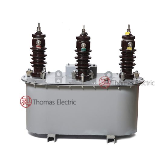
The JLS-20K is a single-phase, indoor/outdoor rated, cast-resin insulated voltage transformer (VT) designed for accurate voltage measurement and reliable protective relay operation in medium-voltage power systems operating at 21kV (IEC standard) or 20kV (domestic system equivalent). This instrument transformer leverages advanced vacuum pressure impregnation (VPI) epoxy resin technology to encapsulate its magnetic core and windings, providing superior dielectric strength, environmental resilience, and long-term operational stability compared to traditional oil-immersed alternatives.
Operating Principle of Cast-Resin Insulation
Cast-resin insulation in the JLS-20K employs a two-component epoxy system cured under vacuum and pressure to eliminate voids and moisture ingress. The primary and secondary windings—wound on a grain-oriented electrical steel (GOES) core—are fully embedded within this solid dielectric matrix. This monolithic structure ensures uniform electric field distribution, suppresses partial discharges below 10 pC at 1.2 × Ur (rated voltage), and provides excellent tracking resistance (CTI ≥ 600 V per IEC 60112). Unlike oil-filled units, the absence of liquid insulation eliminates fire hazards, leakage risks, and the need for periodic oil testing or topping-off, making it ideal for urban substations, indoor switchgear, and environmentally sensitive installations.
Advantages Over Oil-Immersed Designs
The JLS-20K’s cast-resin construction offers distinct engineering advantages: (1) Maintenance-free operation over its 25–30-year service life; (2) Higher mechanical robustness against seismic loads (tested to 0.5g horizontal acceleration); (3) Compact footprint enabling space-constrained retrofits; (4) No SF6 or mineral oil, aligning with EU F-gas regulations and green grid initiatives; and (5) Immediate readiness after installation—no drying-out or degassing procedures required. Additionally, thermal performance is enhanced through optimized resin formulation with high thermal conductivity (≥0.8 W/m·K), allowing continuous operation at ambient temperatures up to +40°C without derating.
Typical Application Overview
Deployed across utility transmission networks, industrial plants, and renewable energy interconnection points, the JLS-20K supports dual-function roles: precision metering (accuracy class 0.2 or 0.5) and protective relaying (accuracy class 3P or 6P). Its design accommodates both grounded-wye and open-delta configurations in 21kV systems. Common use cases include revenue metering at distribution substations, synchronization checks in generator tie-lines, and undervoltage/overvoltage protection in motor control centers. The transformer’s low burden requirement (≤30 VA per accuracy class) ensures compatibility with modern digital relays and smart meters.
Technical Specifications
The JLS-20K adheres strictly to IEC 61869-3 and GB/T 20840.3, with verified performance parameters validated through type, routine, and special tests per clause 7 of the standards.
Rated Electrical Parameters
Primary rated voltage: 21/√3 kV (phase-to-ground in 21kV systems). Secondary rated voltages: 100/√3 V (metering) and/or 100 V (protection), configurable via internal tapping. Standard voltage ratios include 21000/√3 : 100/√3 V and 21000/√3 : 100 V. Accuracy classes: 0.2, 0.5 for metering; 3P, 6P for protection. Rated outputs: 10–100 VA per secondary winding, with thermal short-time withstand capability of 10× rated current for 1 second. Burden tolerance: ±0.25% for class 0.2 at 25–100% of rated burden. Phase displacement: ≤10 minutes for class 0.2 at rated conditions.
Insulation and Environmental Ratings
Power frequency withstand voltage: 50 kV rms (1 min) between HV and ground; 3 kV rms between LV terminals and ground. Lightning impulse withstand: 125 kV peak (1.2/50 μs waveform). Pollution degree: III (creepage distance ≥25 mm/kV). Altitude rating: ≤1000 m above sea level (derating factor 1.1% per 100 m beyond). Ambient temperature range: –25°C to +40°C. Relative humidity: ≤95% non-condensing. Ingress protection: IP00 (requires enclosure when installed indoors; outdoor units feature hydrophobic silicone sheds).
Core and Winding Construction
Magnetic core fabricated from 0.23-mm-thick GOES (M4 grade) laminations, annealed to minimize hysteresis loss (<0.8 W/kg at 1.7 T, 50 Hz). Primary winding: enameled copper wire, 2-layer concentric design with electrostatic shielding. Secondary winding: multi-tap configuration accessible via terminal block, enabling ratio adjustment without rewinding. Resin matrix: cycloaliphatic epoxy with UV stabilizers for outdoor durability. Partial discharge inception voltage: ≥1.8 × Ur (typically >38 kV).
Typical Applications
Substation Secondary Metering
In 21kV distribution substations, the JLS-20K provides the reference voltage signal for revenue-grade kWh meters, demand recorders, and power quality analyzers. Its class 0.2 accuracy ensures billing compliance per IEC 62053-22. For example, in a ring-main unit feeding a commercial district, two JLS-20K units (one per phase) supply 100/√3 V to a three-phase meter, enabling precise energy accounting with <0.5% error across 80–120% load range. The cast-resin body resists condensation in unheated cabinets, eliminating drift caused by oil viscosity changes.
Industrial Power Distribution
Within manufacturing facilities operating at 20kV (domestic equivalent), the JLS-20K interfaces with multifunction protection relays (e.g., overvoltage, undervoltage, loss-of-potential schemes). A typical motor feeder includes one JLS-20K per phase connected in wye, delivering 100 V signals to a SEL-751 relay. The 6P accuracy class guarantees <6% composite error during fault conditions (up to 1.9 × Ur), ensuring reliable tripping while avoiding nuisance operations during transient sags.
Renewable Energy Integration
Solar farms and wind parks connecting to 21kV collector grids utilize the JLS-20K for grid-synchronization and anti-islanding protection. During islanding events, voltage deviations as small as ±5% must be detected within 2 seconds—enabled by the VT’s fast response time (<20 ms) and low phase shift. The transformer’s immunity to DC offset (from inverter harmonics) prevents saturation, maintaining accuracy even with 5% THD on the primary side.
Rural and Suburban Distribution Networks
In remote areas with limited maintenance access, the JLS-20K’s sealed, dry-type design eliminates oil spill risks and reduces lifecycle costs. Mounted on pole-top platforms or pad-mounted switchgear, it supplies voltage signals to SCADA RTUs for remote monitoring. Its wide temperature tolerance (–25°C startup) ensures reliability in alpine or desert climates where oil viscosity would impair performance.
Harsh Environment Installations
Coastal or chemical-industrial zones benefit from the JLS-20K’s corrosion-resistant aluminum flange and silicone-hydrophobic housing. Salt fog testing per IEC 60068-2-11 confirms no degradation after 1000 hours exposure. In mining applications, the unit withstands high dust concentrations (IP5X achievable with optional cover) without compromising insulation integrity.
Compliance with International Standards
IEC 61869-3 Certification Details
The JLS-20K is fully compliant with IEC 61869-3:2011 “Instrument transformers – Part 3: Particular requirements for inductive voltage transformers.” Key conformity aspects include: (1) Defined accuracy limits for metering (classes 0.1 to 1) and protection (3P/6P); (2) Specified test procedures for ratio error, phase displacement, and temperature rise; (3) Mandatory short-circuit withstand verification; and (4) Partial discharge limits (<10 pC at 1.2Ur). Type test reports are issued by accredited laboratories (e.g., KEMA, CESI) and include frequency response analysis confirming flat magnitude response from 45–55 Hz.
Alignment with GB/T 20840.3
For Chinese domestic markets, the JLS-20K meets GB/T 20840.3-2013, which largely harmonizes with IEC 61869-3 but includes additional requirements: (1) Higher lightning impulse level (130 kV vs. 125 kV); (2) Mandatory seismic qualification for regions with intensity ≥7 degrees; and (3) Stricter partial discharge limits (<5 pC at 1.2Ur). The 20kV system voltage designation aligns with GB 156, though the physical unit remains identical to the 21kV IEC version—only nameplate labeling differs.
Key Differences Between IEC and Domestic Standards
While IEC 61869-3 permits ±3% ratio tolerance for protection-class VTs, GB/T 20840.3 requires ±2%. Similarly, IEC allows 10-minute phase error for class 0.5, whereas GB mandates ≤5 minutes. Thermal stability tests under IEC require 4-hour stabilization at 1.1Ur, while GB specifies 6 hours. These differences necessitate dual-certification documentation but do not alter the JLS-20K’s core design, which exceeds both sets of requirements.
On-Site Testing Procedures
Insulation Resistance Test
Conducted using a 2500 V DC megohmmeter between HV-LV+ground and LV-ground. Acceptance criterion: ≥1000 MΩ at 20°C. Temperature correction applied per IEEE 43: Rcorr = Rmeas × 2(40–T)/10. Low readings indicate moisture ingress or resin cracking—requiring drying or replacement. Test performed before energization and after major outages.
Turns Ratio Test
Using an automatic ratio tester (e.g., Omicron CT Analyzer), apply 100–200 V AC to primary and measure secondary voltage. Calculated ratio must match nameplate within ±0.25% for metering class, ±1% for protection class. Deviations suggest winding shorts or incorrect tapping—verified by comparing all three phases in a bank.
Polarity Test
Confirm reducing polarity per IEC 61869-3 Annex B: Apply DC pulse to HV winding; secondary voltage should dip negative on the marked terminal. Incorrect polarity causes 180° phase reversal, leading to metering errors or relay misoperation. Verified during commissioning using a battery-and-galvanometer method or digital phase meter.
Power Frequency Withstand Voltage Test
Apply 50 kV rms at 50 Hz for 60 seconds between HV and grounded LV/enclosure. Leakage current monitored—must remain <10 mA. Any flashover or sudden current rise indicates insulation failure. Performed only during factory acceptance or after repair; omitted in routine field tests to avoid aging.
Open-Circuit Characteristic Test
With secondary open, gradually increase primary voltage from 0 to 1.5 × Ur while recording excitation current. Knee-point voltage (where current rises sharply) must exceed 1.8 × Ur. A depressed knee-point suggests core saturation due to DC bias or mechanical damage. Used diagnostically after through-fault events.
Preventive Maintenance Guide
Periodic Visual and Functional Inspection
Annual inspection includes: (1) Checking for surface cracks, tracking, or discoloration on resin housing; (2) Verifying terminal tightness (torque: 15 N·m for M8 studs); (3) Measuring secondary voltage under load—deviation >±1% from baseline warrants further testing; and (4) Inspecting mounting hardware for corrosion or loosening. In coastal areas, clean sheds with deionized water every 2 years to remove salt deposits.
Long-Term Maintenance Schedule
A 5-year maintenance cycle includes: (1) Full insulation resistance and ratio tests; (2) Partial discharge measurement using HFCT sensors (acceptance: <15 pC at 1.2Ur); (3) Verification of grounding continuity (<0.1 Ω); and (4) Review of historical load data for abnormal heating patterns. After 15 years, consider thermographic scanning during peak load to detect hot spots (>10°C above ambient indicates internal fault).
Fault Diagnosis and Troubleshooting
Common failure modes: (1) Open secondary circuit—causes dangerous overvoltage on primary; mitigated by fusing secondaries per IEC 61869-3 clause 10.3; (2) Core saturation from ferroresonance—prevented by installing damping resistors; (3) Moisture-induced PD—detected via UHF sensors. If secondary voltage drops >5%, isolate and perform turns ratio and excitation tests. Never operate with secondary open—always short before disconnecting meters/relays.
| Maintenance Interval | Tasks |
|---|---|
| Annually | Visual inspection, terminal torque check, secondary voltage verification |
| Every 5 Years | Insulation resistance, ratio test, PD measurement, grounding check |
| After Major Fault | Excitation curve, ratio test, visual inspection for arcing damage |
| Every 15 Years | Thermographic scan, comprehensive dielectric assessment |
Conclusion
The JLS-20K 21kV cast-resin voltage transformer represents a benchmark in medium-voltage instrumentation, combining rigorous adherence to IEC 61869-3 and GB/T 20840.3 with field-proven reliability in diverse operational environments. Its epoxy-encapsulated GOES core delivers exceptional accuracy (class 0.2/0.5 for metering, 3P/6P for protection) while eliminating the fire, environmental, and maintenance liabilities associated with oil-filled designs. With a rated insulation level of 21/50/125 kV and partial discharge performance consistently below 10 pC, the unit ensures decades of stable operation—even under harsh thermal, electrical, and climatic stresses. The transformer’s compact form factor facilitates seamless integration into modern GIS, RMU, and outdoor substation architectures, supporting both legacy electromechanical relays and next-generation digital protection systems. Validated through comprehensive type testing—including thermal, short-circuit, and seismic evaluations—the JLS-20K offers utilities and industrial operators a lifecycle cost advantage through zero-maintenance operation and a projected service life of 25–30 years. As power systems evolve toward smarter, greener infrastructure, this dry-type VT remains a critical enabler of measurement integrity and grid resilience at the 21kV interface.
Q1: Can the JLS-20K be used in a 20kV system?
Yes. While rated at 21kV per IEC 61869-3, the JLS-20K is fully compatible with 20kV domestic systems (per GB 156). The physical unit is identical; only the nameplate voltage designation changes.
Q2: What is the maximum altitude rating?
Standard units are rated for ≤1000 m. For installations above 1000 m, apply a derating factor of 1.1% per 100 m to the rated voltage or request a custom design with increased creepage.
Q3: Is the JLS-20K suitable for indoor installation?
Yes. The base model is rated for both indoor and outdoor use. Indoor installations require mounting within an IP2X enclosure to meet safety clearances.
Q4: What secondary burdens are supported?
Rated outputs range from 10 VA to 100 VA per winding. For class 0.2 accuracy, the connected burden must be within 25–100% of the rated VA.
Q5: How is ferroresonance prevented?
The JLS-20K’s core design minimizes susceptibility, but best practice includes installing a 100–500 Ω damping resistor across one secondary winding in isolated-neutral systems.
Q6: What is the warranty period?
Standard warranty is 5 years, extendable to 10 years with documented preventive maintenance per the manufacturer’s schedule.
Q7: Can multiple secondaries be ordered?
Yes. The JLS-20K can be configured with up to two independent secondary windings (e.g., one for metering at 100/√3 V, one for protection at 100 V).