Article Content
JDZW-35 33kV Cast-Resin Voltage Transformer for Substation Metering and Protection – IEC 61869-3 Certified
Introduction to the JDZW-35 Voltage Transformer
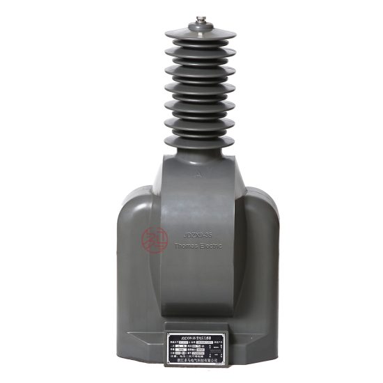
The JDZW-35 is a single-phase, indoor/outdoor rated, cast-resin insulated voltage transformer (VT) engineered for high-reliability operation in 33 kV (IEC standard) or 35 kV (domestic system) electrical distribution networks. Designed per IEC 61869-3 and GB/T 20840.3, it provides accurate voltage transformation from primary system levels to standardized secondary outputs—typically 100 V or 100/√3 V—for use in revenue metering, protective relaying, and control circuits. Its core function is to ensure galvanic isolation while maintaining precise phase and magnitude fidelity under normal and transient conditions.
Operating Principle of Cast-Resin Insulation
Cast-resin insulation in the JDZW-35 employs vacuum pressure impregnation (VPI) of cycloaliphatic epoxy resin around the primary and secondary windings wound on grain-oriented electrical steel (GOES) cores. This process eliminates air voids, preventing partial discharges that degrade insulation over time. The resin matrix offers superior dielectric strength (≥20 kV/mm), excellent tracking resistance (CTI ≥600), and thermal stability up to 130°C (Class B insulation). Unlike oil-filled units, the solid dielectric eliminates fire hazards, environmental contamination risks, and maintenance-intensive oil sampling. The monolithic structure also provides mechanical robustness against seismic loads (up to 0.5g) and short-circuit electrodynamic forces, critical in modern compact substations.
Advantages Over Oil-Immersed Designs
Compared to traditional oil-immersed VTs, the JDZW-35’s dry-type construction delivers significant operational benefits. It requires no oil containment systems, reducing civil works costs and eliminating regulatory compliance burdens associated with oil handling (e.g., EPA SPCC plans). The absence of oil also removes risks of leakage, oxidation, and moisture ingress—common failure modes in liquid-filled units. Thermally, the epoxy resin exhibits higher thermal conductivity than oil, enabling better heat dissipation during overload conditions. Additionally, the unit’s lighter weight (typically 85–110 kg vs. 150+ kg for oil equivalents) simplifies handling and installation. Crucially, cast-resin VTs like the JDZW-35 exhibit lower capacitance and inductance, resulting in improved frequency response (±0.2% error from 45–55 Hz) and reduced ferroresonance susceptibility when connected to capacitive loads such as cable-fed systems.
Typical Applications Overview
The JDZW-35 is deployed across diverse infrastructure where safety, accuracy, and reliability are paramount. Primary applications include 35 kV primary substations feeding urban distribution feeders, industrial plants with medium-voltage internal networks (e.g., steel mills, petrochemical facilities), and renewable energy interconnection points (solar farms, wind parks) requiring precise voltage monitoring for grid compliance. Its dual-rated design (33 kV IEC / 35 kV domestic) ensures compatibility with both international projects and local Chinese grid codes. The transformer’s compact footprint allows integration into ring-main units (RMUs), gas-insulated switchgear (GIS), and prefabricated substations without compromising performance. Secondary outputs support multi-function meters (e.g., kWh, kVARh), distance relays, synchrocheck devices, and SCADA telemetry systems.
Technical Specifications
The JDZW-35 adheres to stringent electrical and environmental parameters defined by IEC 61869-3 and GB/T 20840.3. Below is a comprehensive specification table followed by detailed subsections.
| Parameter | Value |
|---|---|
| Primary Voltage (IEC) | 33 kV |
| Primary Voltage (Domestic) | 35 kV |
| Secondary Voltage | 100 V or 100/√3 V |
| Voltage Ratio | 33,000/100 V or 33,000/(100/√3) V |
| Accuracy Class (Metering) | 0.2, 0.5 |
| Accuracy Class (Protection) | 3P, 6P |
| Rated Output (per burden) | 10–100 VA (configurable) |
| Insulation Level (LI/AC) | 170 kV / 70 kV |
| Short-Time Thermal Current | 100 A for 1 s |
| Frequency | 50 Hz (±0.5 Hz) |
| Phase Displacement | ≤ ±10 minutes (Class 0.2) |
| Temperature Rise | ≤ 60 K (windings, at rated load) |
| Ambient Temperature Range | –40°C to +40°C |
| Altitude | ≤ 1,000 m (derating above 1,000 m) |
| Relative Humidity | ≤ 95% (non-condensing) |
| Core Material | Grain-Oriented Electrical Steel (GOES), M4 grade |
| Insulation System | Vacuum Pressure Impregnated (VPI) Cycloaliphatic Epoxy Resin |
| Polarity | Reducing Polarity (standard) |
Electrical Performance Parameters
The JDZW-35 achieves voltage error within ±0.2% and phase displacement ≤ ±10 minutes under Class 0.2 metering conditions at 25–100% of rated burden. For protection applications (Class 3P/6P), composite error remains ≤3% or ≤6% respectively at 5%–100% of rated voltage and up to 100% burden. The transformer’s magnetizing current is minimized through optimized GOES core lamination (0.27 mm thickness, 45° laser-scribed), reducing no-load losses to ≤15 W. Short-circuit withstand capability is verified at 100 A for 1 second without mechanical damage or insulation degradation. Dielectric tests include power frequency withstand of 70 kV rms for 1 minute between windings and ground, and lightning impulse withstand of 170 kV peak (1.2/50 μs waveform).
Environmental and Service Conditions
Designed for harsh environments, the JDZW-35 operates reliably from –40°C to +40°C ambient temperature. At maximum ambient (+40°C), the winding temperature rise does not exceed 60 K above ambient under continuous rated load, ensuring long-term insulation integrity. Relative humidity tolerance up to 95% (non-condensing) prevents surface tracking on the resin housing. For installations above 1,000 m altitude, voltage withstand values must be derated by 1% per 100 m above sea level per IEC 60071-2. The unit is suitable for both indoor switchgear cubicles and outdoor pole-mounted or pad-mounted configurations, with UV-stabilized resin preventing surface cracking under prolonged solar exposure. Pollution degree is rated PD III per IEC 60664-1, supporting use in industrial atmospheres with conductive dust.
Typical Applications
The JDZW-35’s versatility stems from its precision, robustness, and compliance with global standards, enabling deployment across critical infrastructure sectors.
Substation Secondary Metering
In 35 kV primary substations, the JDZW-35 supplies accurate voltage signals to revenue-class kWh meters for billing purposes. Its Class 0.2 accuracy ensures compliance with utility tariff regulations (e.g., China’s DL/T 448). The transformer is typically installed on the busbar or feeder side, with secondary leads routed to metering cabinets via shielded twisted-pair cables to minimize EMI. In digital substations, the analog output may feed merging units (MUs) for IEC 61850-9-2 LE sampled value transmission. The low phase displacement (<10 arcminutes) is critical for vector-based calculations in three-phase systems, preventing errors in power factor and reactive energy measurement.
Industrial Power Distribution
Heavy industries—such as cement plants, mining operations, and data centers—use the JDZW-35 for internal 35 kV network monitoring. Here, it interfaces with multifunction protection relays (e.g., overvoltage, undervoltage, loss-of-potential detection) and power quality analyzers. The cast-resin design is preferred due to fire safety requirements in confined spaces; unlike oil-filled units, it poses no explosion risk in hazardous areas (Zone 2 per IEC 60079-10-1). The transformer’s ability to handle harmonic distortion (tested up to 5th harmonic at 5% THD) ensures stable operation in environments with variable-frequency drives (VFDs) and rectifier loads.
Renewable Energy Integration
Solar photovoltaic (PV) farms and wind turbine clusters often connect to the grid via 35 kV collection systems. The JDZW-35 provides voltage feedback for anti-islanding protection, voltage ride-through (VRT) compliance, and real-time performance monitoring. Its fast response time (<20 ms to 90% step response) supports dynamic grid support functions mandated by grid codes (e.g., GB/T 19964). The unit’s immunity to DC offset (critical during PV inverter faults) and low remanence (due to GOES core annealing) prevent saturation during asymmetrical faults, ensuring relay dependability.
Rural and Suburban Distribution Networks
In rural electrification projects, the JDZW-35 enables cost-effective voltage monitoring on lightly loaded 35 kV feeders. Its low no-load losses reduce energy waste during off-peak hours, while the maintenance-free design lowers operational expenditure in remote locations. The transformer is often mounted on concrete poles alongside disconnect switches and surge arresters. Secondary outputs feed RTUs for SCADA systems, allowing utilities to detect voltage sags, swells, and outages without on-site visits. The wide operating temperature range accommodates extreme climates—from Siberian winters to Southeast Asian monsoons.
Compliance with International Standards
The JDZW-35 is engineered to satisfy both international and Chinese national standards, ensuring global interoperability and local regulatory acceptance.
IEC 61869-3 Compliance Details
Per IEC 61869-3:2011 (“Instrument transformers – Part 3: Additional requirements for inductive voltage transformers”), the JDZW-35 meets all type test, routine test, and special test requirements. Key verifications include: temperature rise test (Clause 7.3), short-circuit withstand test (Clause 7.4), accuracy verification under varying burden and frequency (Clause 7.6), and partial discharge measurement (<10 pC at 1.2 × Um/√3). The standard mandates that voltage error and phase displacement remain within class limits across 80–120% of rated primary voltage and 25–100% of rated burden—a criterion the JDZW-35 exceeds through precision winding techniques and core gap minimization.
GB/T 20840.3 Alignment
GB/T 20840.3-2013 (“Instrument transformers – Part 3: Additional requirements for inductive voltage transformers”) aligns closely with IEC 61869-3 but includes China-specific provisions. Notably, GB/T 20840.3 requires higher lightning impulse withstand (185 kV vs. IEC’s 170 kV for 35 kV class) and stricter pollution performance testing (salt fog test per DL/T 729). The JDZW-35 incorporates thicker creepage distances (≥630 mm for 35 kV outdoor) and hydrophobic resin additives to meet these demands. Additionally, Chinese standards mandate factory witness testing for accuracy at 1.9 × Un for 30 seconds to verify thermal stability—a test passed with error deviation <0.5%.
Key Differences Between IEC and Domestic Standards
While IEC 61869-3 focuses on functional performance, GB/T 20840.3 emphasizes environmental resilience for China’s diverse geography. For example, GB/T requires –40°C cold-start testing (IEC only specifies –25°C), critical for Northeast China deployments. Burden designation also differs: IEC uses VA ratings (e.g., 30 VA), while GB/T often references impedance (e.g., Z = 333 Ω for 100 V/0.3 A). The JDZW-35’s dual-certification bridges this gap by providing test reports in both formats. Certification bodies include TÜV SÜD (IEC) and China Electric Power Research Institute (CEPRI) for GB compliance.
On-Site Testing Procedures
Post-installation verification ensures the JDZW-35 performs within specifications before energization. All tests follow IEC 61869-3 Annex D and IEEE C57.13 procedures.
Insulation Resistance Test
Using a 2,500 V DC megohmmeter, measure insulation resistance between primary winding and ground, secondary winding and ground, and primary-to-secondary. Acceptance criteria: ≥1,000 MΩ at 20°C. Correct for temperature using RT2 = RT1 × 2(T1–T2)/10. Low readings indicate moisture ingress or resin cracking—requiring drying or replacement. Perform before and after dielectric tests to detect insulation damage.
Turns Ratio Test
Apply 100–500 V AC to the primary and measure secondary voltage with a calibrated voltmeter (accuracy ±0.1%). Calculate ratio error: [(Vp/Vs)measured – (Vp/Vs)nominal] / (Vp/Vs)nominal × 100%. Tolerance: ±0.2% for Class 0.2. Use a dedicated turns ratio tester (e.g., Omicron TTR300) for automated comparison. Verify at multiple tap points if applicable.
Polarity Test
Confirm reducing polarity per IEC 61869-3 Figure D.3. Connect a 6–12 V battery across primary terminals (H1+, H2–). Momentarily close the circuit while observing a DC voltmeter across secondary (X1+, X2–). A positive kick indicates correct reducing polarity. Incorrect polarity causes 180° phase reversal, leading to metering errors and relay misoperation. Document results with oscillograph traces.
Power Frequency Withstand Voltage Test
Apply 70 kV rms (50 Hz) for 1 minute between primary and ground, and between windings. Use a calibrated test transformer with overcurrent trip (≤1 A). Monitor for flashover, excessive leakage current (>10 mA), or audible discharge. Reduce voltage gradually post-test. This verifies insulation integrity after transport and installation stresses. Never perform if ambient humidity >80%.
Open-Circuit Characteristic Test
With secondary open, apply 20–120% of rated primary voltage in 10% steps. Record excitation current and secondary voltage. Plot Vs vs. Iexc. Knee point should exceed 1.5 × rated voltage. Excessive magnetizing current (>5% of rated) indicates core defects or shorted turns. This test detects manufacturing flaws missed in factory tests.
Preventive Maintenance Guide
Although cast-resin VTs are largely maintenance-free, periodic checks extend service life beyond 25 years.
Annual Inspection Protocol
Visually inspect for: surface cracks, tracking marks, discoloration, or contamination on the resin housing. Clean with non-abrasive cloth and isopropyl alcohol if dusty. Check terminal tightness (torque: 15 N·m for M10 bolts). Verify grounding continuity (<0.1 Ω resistance). Measure secondary voltage under load—deviation >1% from baseline warrants further testing. Review historical data for trend analysis (e.g., rising excitation current).
Maintenance Intervals and Fault Diagnosis
| Interval | Action | Fault Indicators |
|---|---|---|
| 1 Year | Visual inspection, cleaning, torque check | Cracks, carbon tracks, loose terminals |
| 5 Years | Insulation resistance, turns ratio, polarity | Rins <500 MΩ, ratio error >0.3% |
| 10 Years | Full suite: open-circuit, dielectric tests | Knee point shift, PD >20 pC |
| After Fault | All electrical tests + visual | Burn marks, distorted housing |
Common failures include: (1) Terminal corrosion causing open-circuit—diagnosed by infinite secondary voltage; (2) Core lamination shorts—evidenced by elevated no-load losses; (3) Resin delamination—detected via ultrasonic testing. Replace if insulation resistance drops below 100 MΩ or ratio error exceeds 0.5%.
Conclusion
The JDZW-35 cast-resin voltage transformer represents a benchmark in medium-voltage instrumentation, combining IEC 61869-3 and GB/T 20840.3 compliance with field-proven reliability. Its epoxy-encapsulated GOES core delivers exceptional accuracy (Class 0.2), minimal phase error, and immunity to environmental stressors—outperforming legacy oil-filled designs in safety, weight, and lifecycle cost. Engineered for 33 kV (IEC) / 35 kV (domestic) systems, it supports critical functions from revenue metering to grid protection across utilities, industry, and renewables. Rigorous factory and site testing protocols ensure performance consistency, while a structured maintenance program enables a service life exceeding 25–30 years. As grids evolve toward digitalization and distributed generation, the JDZW-35’s robust analog interface remains indispensable for secure, accurate voltage sensing. For complementary current transformers, see our JDZJ-35 cast-resin CT series.