Article Content
LSZY-35 33kV Cast-Resin Voltage Transformer for Substation Metering and Protection – IEC 61869-3 Certified
Introduction to the LSZY-35 Voltage Transformer
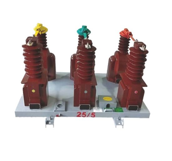
The LSZY-35 is a single-phase, inductive-type cast-resin voltage transformer (VT) engineered for high-reliability operation in 33 kV (IEC-rated) or 35 kV (domestic system) electrical networks. Designed in strict compliance with IEC 61869-3 and GB/T 20840.3, this instrument transformer provides accurate voltage scaling for both metering and protective relaying functions in medium-voltage substations and industrial facilities.
Operating Principle of Cast-Resin Insulation
Cast-resin insulation in the LSZY-35 employs vacuum pressure impregnation (VPI) of cycloaliphatic epoxy resin around the primary and secondary windings, followed by high-temperature curing. This process eliminates air voids and moisture ingress pathways, resulting in a homogeneous dielectric structure with superior partial discharge resistance (<5 pC at 1.2 × Ur). The solid insulation system ensures stable performance under thermal cycling from –40°C to +40°C ambient conditions and withstands impulse voltages up to 170 kV (BIL). Unlike oil-filled alternatives, the absence of liquid dielectric eliminates fire hazards, environmental contamination risks, and maintenance-intensive oil sampling procedures. The resin matrix also provides mechanical rigidity, reducing winding displacement during short-circuit transients.
Advantages Over Oil-Immersed Designs
Compared to traditional oil-immersed VTs, the LSZY-35 offers significant operational and safety benefits. Its dry-type construction eliminates flammability concerns, making it suitable for indoor installations near personnel or sensitive equipment. The hermetically sealed design requires no periodic oil level checks, gas analysis, or bushing maintenance. Weight is reduced by approximately 30%, simplifying handling and mounting on switchgear structures. Furthermore, the cast-resin body exhibits excellent hydrophobicity and UV resistance, ensuring long-term outdoor durability without degradation of insulation properties. Thermal stability is enhanced due to the high thermal conductivity of the filled epoxy system (0.8–1.2 W/m·K), which efficiently dissipates heat generated during continuous operation at rated burden.
Typical Applications Overview
The LSZY-35 is deployed across diverse power infrastructure segments where precise voltage transformation and system reliability are critical. Primary use cases include utility-owned 35 kV distribution substations for revenue metering and distance protection, industrial plants with internal 33 kV networks requiring harmonic monitoring, and renewable energy interconnection points (e.g., solar farms) needing synchronized voltage signals for grid compliance. Its dual-winding secondary configuration supports simultaneous connection to energy meters (Class 0.5 or 0.2) and overvoltage relays (Class 3P or 6P), eliminating the need for multiple transformers. The unit’s compact footprint (typically 450 mm height × 280 mm base) facilitates retrofitting into existing switchgear bays originally designed for oil-filled units.
Technical Specifications
The LSZY-35 delivers precision voltage transformation under defined electrical and environmental parameters, ensuring compatibility with global substation architectures.
Rated Electrical Parameters
The primary rated voltage is 33 kV (IEC standard), corresponding to a maximum system voltage of 36 kV. The domestic equivalent is designated as 35 kV, reflecting nominal network voltage in certain regional grids. Standard secondary voltages are 100 V or 100/√3 V for phase-to-ground connections. Common voltage ratios include 33,000/100 V, 33,000/√3 / 100/√3 V, and 35,000/100 V. Accuracy classes are available per IEC 61869-3: Class 0.2 and 0.5 for metering; Class 3P and 6P for protection. Rated outputs range from 30 VA to 100 VA per secondary winding, with thermal short-time current rating of 100 A for 1 second. The insulation coordination follows IEC 60071-1: power frequency withstand voltage of 70 kV (rms, 1 min) between HV and earth, and lightning impulse withstand voltage of 170 kV (peak, 1.2/50 μs wave).
Environmental and Mechanical Ratings
Designed for both indoor and outdoor service, the LSZY-35 operates reliably under ambient temperatures from –40°C to +40°C, relative humidity up to 95% (non-condensing), and altitudes ≤1000 m above sea level. For installations above 1000 m, derating factors apply per IEC 60071-2 (e.g., 1.1% reduction in withstand voltage per 100 m above 1000 m). The housing is constructed from UV-stabilized cycloaliphatic epoxy with tracking resistance ≥600 V (CTI). Creepage distance exceeds 25 mm/kV for pollution degree 3 environments (IEC 60815), ensuring flashover resistance in coastal or industrial atmospheres. Mounting is via M16 threaded studs with torque specification of 80 N·m ±10%.
Core and Winding Construction
The magnetic circuit utilizes grain-oriented electrical steel (GOES) laminations with thickness of 0.27 mm and specific loss ≤0.95 W/kg at 1.7 T, 50 Hz. This minimizes no-load losses and improves accuracy under light-load conditions. Primary windings consist of enameled copper wire with Class F insulation (155°C thermal class), while secondary windings use double-insulated stranded copper conductors rated for 600 V. Inter-turn and layer insulation employ Nomex® aramid paper combined with epoxy resin, providing dielectric strength >20 kV/mm. The entire assembly undergoes post-curing at 130°C for 8 hours to relieve mechanical stresses and enhance dimensional stability.
Typical Applications
The LSZY-35 serves as a foundational component in modern power systems requiring dependable voltage sensing.
Substation Secondary Metering
In 35 kV utility substations, the LSZY-35 supplies scaled voltage signals to revenue-class energy meters (e.g., IEC 62053-22 compliant). With accuracy class 0.2S, it ensures billing precision within ±0.2% error at 20–120% of rated voltage and 25–100% of rated burden. Dual secondary windings allow one output to feed kWh meters while the other connects to power quality analyzers for harmonic distortion monitoring (up to 50th order). The low phase error (<10 minutes at 0.2 class) maintains synchronization accuracy for time-of-use tariff calculations. Installation typically occurs on the busbar side of circuit breakers to capture pre-fault voltage conditions for event analysis.
Industrial Power Distribution
Large manufacturing facilities operating internal 33 kV networks deploy the LSZY-35 for motor protection and load management. In steel mills or chemical plants, it interfaces with multifunction relays (e.g., Siemens 7SJ62) to detect undervoltage, overvoltage, and phase unbalance conditions that could damage induction motors. The Class 3P accuracy ensures relay operation within ±3% error during fault conditions (e.g., 1.9 × Ur for 30 seconds). Its robust cast-resin housing resists chemical vapors and airborne particulates common in industrial settings, eliminating the risk of oil leakage onto production floors.
Renewable Energy Integration
Solar photovoltaic and wind farms connecting to 35 kV grids utilize the LSZY-35 for grid code compliance. It provides voltage reference signals to inverters for reactive power control (Q(V) droop) and to SCADA systems for remote monitoring. During islanding events, the VT enables detection of voltage magnitude and frequency deviations beyond permissible limits (e.g., ENTSO-E requirements). The fast transient response (<2 ms rise time) ensures timely tripping during anti-islanding tests. Units installed in desert environments benefit from the resin’s resistance to thermal shock from diurnal temperature swings exceeding 50°C.
Rural and Suburban Distribution Networks
In remote areas with limited maintenance access, the LSZY-35’s maintenance-free design reduces lifecycle costs. Mounted on pole-top reclosers or pad-mounted switchgear, it enables automated sectionalizing based on voltage collapse detection. The high insulation level (170 kV BIL) protects against lightning-induced surges common in overhead line networks. Utilities leverage its long service life (>25 years) to defer capital expenditures in aging infrastructure upgrades. The standardized 100 V secondary simplifies integration with legacy electromechanical relays still in service.
Compliance with International Standards
The LSZY-35 meets stringent global and regional requirements for instrument transformer performance and safety.
IEC 61869-3 Certification Details
Compliance with IEC 61869-3:2011 (“Instrument transformers – Part 3: Additional requirements for inductive voltage transformers”) governs all critical performance aspects. This includes verification of accuracy limits under defined burdens (e.g., cos φ = 0.8 lagging for metering, 1.0 for protection), temperature rise tests (≤55 K for windings at 1.2 × Ur), and short-circuit withstand capability. The standard mandates partial discharge measurements below 10 pC at 1.2 × Ur/√3 during factory testing. Electromagnetic compatibility (EMC) immunity to 1 MHz damped oscillatory waves (IEC 61000-4-12) ensures reliable operation near switching transients. Each unit receives a test certificate documenting ratio error, phase displacement, and insulation test results traceable to national metrology institutes.
Alignment with GB/T 20840.3
The Chinese national standard GB/T 20840.3-2013 aligns closely with IEC 61869-3 but includes region-specific provisions. Key differences involve altitude correction factors (GB allows up to 3000 m with linear derating) and creepage distance requirements (≥31 mm/kV for heavy pollution zones). The standard specifies additional type tests for seismic resilience (horizontal acceleration 0.3g) relevant to earthquake-prone regions like Sichuan. While IEC permits synthetic testing for thermal stability, GB/T requires direct loading tests at 1.2 × Ur for 8 hours. Manufacturers must obtain China Compulsory Certification (CCC) mark, involving factory audits by CNAS-accredited bodies.
Testing and Certification Protocols
Full type testing per IEC 61869-3 includes: temperature rise (resistance method), short-circuit withstand (100 A for 1 s), impulse voltage (170 kV peak), and power frequency withstand (70 kV rms). Routine tests performed on every unit comprise: visual inspection, winding resistance measurement (±2% tolerance), ratio and polarity verification (±0.1% error), and insulation resistance (>10,000 MΩ at 2500 V DC). Third-party certification by organizations like KEMA, CESI, or CEPREI validates compliance. Test reports must include waveform captures of ratio error under harmonic distortion (e.g., 5% 3rd harmonic injection) to demonstrate immunity to grid non-sinusoidal conditions.
On-Site Testing Procedures
Field commissioning requires verification of key parameters to ensure safe and accurate operation.
Insulation Resistance Test
Using a 2500 V megohmmeter, measure insulation resistance between HV terminal and grounded case, and between LV terminals and case. Acceptance criterion: ≥10,000 MΩ at 20°C. Correct readings to 20°C using R20 = Rt × 1.5(t–20)/10. Values below 1000 MΩ indicate moisture ingress or resin cracking requiring further investigation via tan δ measurement.
Turns Ratio Test
Apply 100–200 V AC to the primary winding and measure secondary voltage with a calibrated voltmeter (accuracy class 0.1). Calculate actual ratio and compare to nameplate. Tolerance: ±0.1% for metering class, ±0.3% for protection class. Use a dedicated ratio tester (e.g., Omicron CT Analyzer) for automated comparison against factory data stored in QR code on nameplate.
Polarity Verification
Confirm reducing polarity using the DC kick method: connect a 6 V battery momentarily between HV terminal (positive) and ground. Observe momentary deflection of analog voltmeter connected to LV terminals (positive to polarity-marked terminal). Deflection must be upscale. Incorrect polarity causes 180° phase shift, leading to false tripping in directional relays.
Power Frequency Withstand Test
Apply 70 kV rms at 50 Hz between HV terminal and grounded case for 1 minute using a portable test set. Monitor for flashover, excessive leakage current (>1 mA), or audible discharge. Pre-test: ensure ambient humidity <80% and surface dryness. Post-test: repeat insulation resistance to confirm no degradation.
Open-Circuit Characteristic Test
Gradually increase primary voltage from 0 to 1.5 × Ur while measuring secondary voltage and excitation current. Plot Vs vs Iexc. Knee point should exceed 1.3 × Ur. Excessive excitation current (>5 mA at 1.2 × Ur) indicates core saturation or turn-to-turn faults. Compare curve shape to factory baseline to detect winding deformation.
Preventive Maintenance Guide
Although maintenance-free by design, periodic checks extend service life and prevent unexpected failures.
Annual Visual and Electrical Inspection
Inspect housing for cracks, tracking marks, or UV degradation (chalky surface). Clean with non-abrasive cloth and isopropyl alcohol if contaminated. Verify terminal tightness (80 N·m torque). Measure insulation resistance and compare to baseline; a 50% drop warrants detailed diagnostics. Check grounding continuity (<0.1 Ω resistance). Document findings in asset management system for trend analysis.
Five-Year Comprehensive Assessment
Perform partial discharge measurement using IEC 60270-compliant equipment. Acceptable level: <10 pC at 1.2 × Ur/√3. Conduct tan δ test at 10 kV; values >0.5% indicate moisture absorption. Re-verify ratio and polarity. If installed in corrosive environments, inspect mounting hardware for galvanic corrosion. Replace silica gel breathers if present (though rare in cast-resin designs).
Fault Diagnosis and Troubleshooting
Common failure modes include: (1) Secondary open-circuit during operation—causes dangerous overvoltage on primary; always short secondary before disconnecting loads. (2) Core saturation from ferroresonance—mitigate with damping resistors per IEC TR 61869-102. (3) Resin delamination—detected via ultrasonic testing showing impedance mismatch. Maintain spare VTs with identical ratio and burden ratings to minimize outage duration during replacements.
Conclusion
The LSZY-35 cast-resin voltage transformer represents a technically mature solution for accurate and reliable voltage transformation in 33 kV (IEC) / 35 kV (domestic) power systems. Its epoxy resin insulation system eliminates the fire, environmental, and maintenance liabilities associated with oil-filled alternatives while delivering superior dielectric performance under harsh operating conditions. Compliance with IEC 61869-3 and GB/T 20840.3 ensures interoperability with global protection and metering schemes, supported by rigorous factory and field testing protocols. The use of GOES core material and precision winding techniques guarantees accuracy stability over decades of service, even under harmonic-rich grid conditions. With a design life exceeding 25–30 years and minimal preventive maintenance requirements, the LSZY-35 offers compelling lifecycle cost advantages for utilities and industrial operators alike. Its dual secondary configuration, robust environmental ratings, and proven field reliability make it an optimal choice for new installations and legacy system upgrades where safety, precision, and longevity are paramount. As power networks evolve toward smarter, more resilient architectures, the LSZY-35 remains a cornerstone component for trustworthy voltage sensing in critical infrastructure.