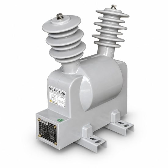
Product Overview
The FDGE11 outdoor discharge coil is a dry-type epoxy resin cast device designed for high-voltage shunt capacitor banks in 6kV to 12kV power systems. Connected in parallel with the capacitor bank, it provides a controlled discharge path after switching operations to reduce residual voltage to safe levels within the required discharge time.
Unlike conventional voltage transformers, the primary function of the FDGE11 discharge coil is capacitor discharge. The secondary winding provides voltage indication, measurement, or residual-voltage signals for protection systems when specified.
Key Features:
- Outdoor single-phase, fully sealed dry-type construction
- Vacuum-cast epoxy resin insulation for reliable outdoor performance
- Primary voltage options: 6.6/√3, 7.2/√3, 11/√3 and 12/√3 kV
- Matched capacitor capacity: 1.7, 2.5 and 3.4 Mvar
- Insulation levels: 7.2/32/60 kV or 12/42/75 kV by model
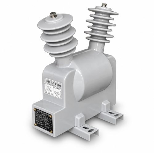
Product Display
Model Designation
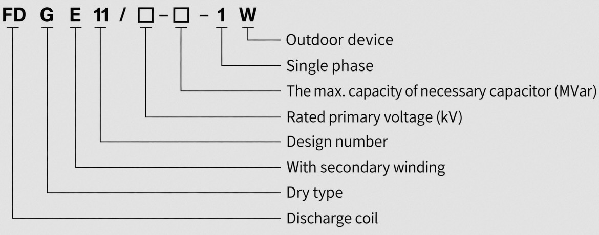
The FDGE11 model designation follows a standardized coding system:
Example: FDGE11/11/√3-2.5-1W identifies an outdoor single-phase dry-type discharge coil with secondary winding, an 11/√3 kV rated primary voltage configuration and a 2.5 Mvar matched capacitor capacity.
Service Conditions
- Installation: Outdoor
- Rated Frequency: 50 Hz standard; 60 Hz configuration available upon technical confirmation
- Ambient Temperature: -40°C to +40°C
- Altitude: ≤ 3000 m
- Environmental Requirements: No corrosive gas, vapor, conductive dust, or explosive dust
- Mechanical Requirements: No severe mechanical vibration
Construction
The FDGE11 discharge coil uses a fully sealed post-type structure with vacuum-cast epoxy resin insulation. The core and windings are encapsulated in resin to form a compact dry-type insulation system suitable for outdoor service.
Construction Advantages: Resistance to moisture, electrical tracking, UV exposure and ageing, sealed secondary terminal compartment to reduce water ingress, oil-free design for simplified maintenance, reference creepage distance > 420 mm, secondary load power factor cos φ = 0.8 lagging.
Technical Data
| Model | Rated
Voltage Ratio |
Accuracy Class
Rated Output |
Matched
Capacitor / Discharge Capacity |
Rated
Insulation Level |
|---|---|---|---|---|
| FDGE11/6.6/√3-1.7-1W | 6.6/√3 kV / 0.1 kV | 0.2 / 20 VA 0.5 / 50 VA 1.0 / 100 VA |
1.7 Mvar | 7.2/32/60 kV |
| FDGE11/7.2/√3-1.7-1W | 7.2/√3 kV / 0.1 kV | 0.2 / 20 VA 0.5 / 50 VA 1.0 / 100 VA |
1.7 Mvar | 7.2/32/60 kV |
| FDGE11/11/√3-1.7-1W | 11/√3 kV / 0.1 kV | 0.2 / 20 VA 0.5 / 50 VA 1.0 / 100 VA |
1.7 Mvar | 12/42/75 kV |
| FDGE11/11/√3-2.5-1W | 11/√3 kV / 0.1 kV | 0.2 / 20 VA 0.5 / 50 VA 1.0 / 100 VA |
2.5 Mvar | 12/42/75 kV |
| FDGE11/11/√3-3.4-1W | 11/√3 kV / 0.1 kV | 0.2 / 20 VA 0.5 / 50 VA 1.0 / 100 VA |
3.4 Mvar | 12/42/75 kV |
| FDGE11/12/√3-1.7-1W | 12/√3 kV / 0.1 kV | 0.2 / 20 VA 0.5 / 50 VA 1.0 / 100 VA |
1.7 Mvar | 12/42/75 kV |
| FDGE11/12/√3-2.5-1W | 12/√3 kV / 0.1 kV | 0.2 / 20 VA 0.5 / 50 VA 1.0 / 100 VA |
2.5 Mvar | 12/42/75 kV |
| FDGE11/12/√3-3.4-1W | 12/√3 kV / 0.1 kV | 0.2 / 20 VA 0.5 / 50 VA 1.0 / 100 VA |
3.4 Mvar | 12/42/75 kV |
Standards
The FDGE11 series is designed for high-voltage shunt capacitor applications. The applicable Chinese industry standard DL/T 653-2023 covers discharge coils for high-voltage shunt capacitor installations and replaces DL/T 653-2009.
Installation & Dimensions
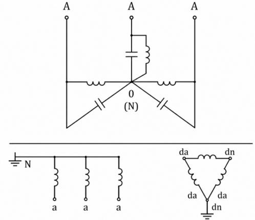
The FDGE11 discharge coil is installed outdoors and connected in parallel with the shunt capacitor bank. The high-voltage winding is connected across the capacitor bank terminals. Secondary terminals are connected according to the specified measurement or protection circuit.
Installation Diagram
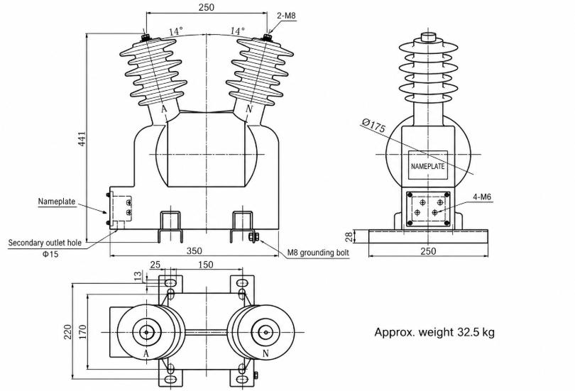
Wiring Diagram

Installation Features: Fully sealed post-type structure for outdoor mounting, sealed secondary terminal compartment, grounding point provided, oil-free design for simplified maintenance.