Product Overview
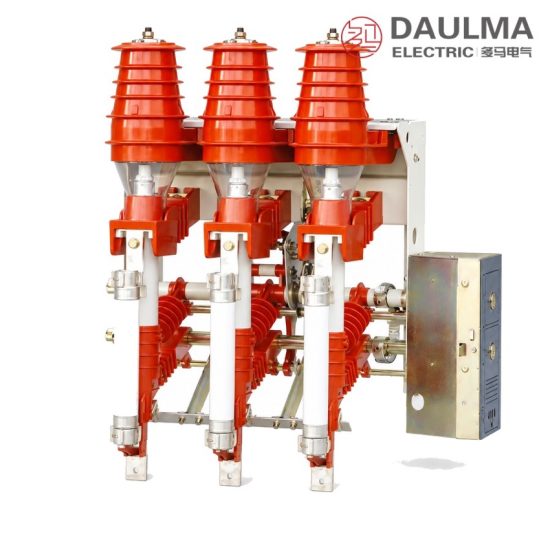
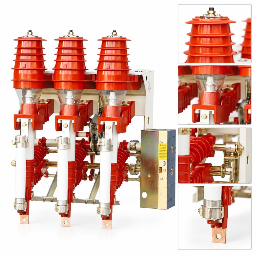
The FKN12A-12D indoor air-puff load break switch and the FKRN12A-12D switch-fuse combination unit are three-phase switching units for distribution systems of 12 kV and below. They control and protect transformers, cables and overhead line sections, and are used mainly in urban and rural terminal substations, box substations, and ring-network or double-radial supply units. The load break switch makes and breaks load current and overload current; in the combination unit the circuit is completed with back-up fuses, so line short-circuit current is cleared as well. Switch, earthing switch, fuses and mechanism are carried on a single frame, which keeps the unit compact and easy to install.
Product Display
Model Designation
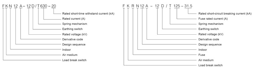
Model format: FKN12A-12D/T 630-20 (load break switch) and FKRN12A-12D/T 125-31.5 (switch-fuse combination unit)
- F: load break switch; K: air medium, air-puff design; N: indoor type
- 12: design sequence number; A: derivative code; 12: rated voltage, kV
- D: with earthing switch; T: spring mechanism
- 630: rated current, A; 20: rated short-time withstand current, kA
- R: combined with fuse; 125: rated current of the fuse, A; 31.5: rated short-circuit breaking current, kA
Service Conditions
- Ambient temperature: +40 °C upper, -25 °C lower
- Altitude: not more than 1000 m
- Relative humidity: daily average not more than 95%, monthly average not more than 90%
- Seismic intensity: not more than 8 degrees
- Site condition: no fire, explosion hazard, chemical corrosion or violent vibration
- Pollution level: II
Construction
Load break switch, earthing switch, fuses and mechanism are mounted on one frame, which can be combined flexibly and keeps the unit compact and easy to install. The break is arranged upright, so the dynamic and thermal stability ratings are high and each operation is completed in one stroke.
Static contact covers provide structural isolation inside the ring-main cubicle, which removes the need for inter-phase insulation boards and gap insulation plates and helps resist internal arcing faults. After the load break switch opens, a shutter closes automatically over the open gap, improving protection for personnel working on the panel.
Technical Data
| No. | Item | Unit | Value |
|---|---|---|---|
| 1 | Rated voltage | kV | 12 |
| 2 | Rated current of the load break switch | A | 630 |
| 3 | Rated short-time withstand current | kA | 20 |
| 4 | Rated current of the fuse, combination unit | A | 125 |
| 5 | Rated short-circuit breaking current, combination unit | kA | 31.5 |
| 6 | Overall width | mm | 868 |
| 7 | Overall height | mm | 940 |
| 8 | Mass | kg | 70 |
Standards
The source page does not quote a standard number for this switch. The usual references for indoor high-voltage load break switches are IEC 62271-102 / IEC 60265-1 and GB/T 3804; confirm the applicable edition with the factory when ordering.
Installation & Dimensions
Installation Diagram
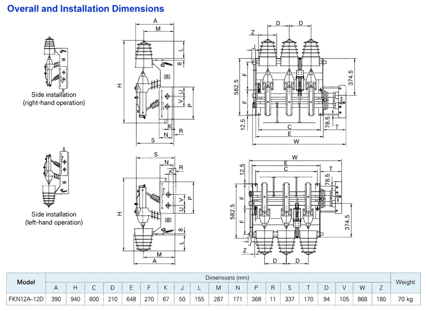
The three-pole unit is bolted into the cubicle frame across an overall width of 868 mm with an overall height of 940 mm and a mass of 70 kg; check busbar and cable clearances against the approved outline drawing before the frame is torqued. Charge the spring, confirm the closed, open and earthed positions on all three poles, verify the interlocking between load break switch, earthing switch and fuse compartment, and on the combination unit fit the specified 125 A back-up fuse and confirm the striker engagement.
| Dimension | Value |
|---|---|
| Overall width (W) | 868 mm across the three poles |
| Overall height (H) | 940 mm including the live-part covers |
| Phase spacing (D) | 210 mm between adjacent poles |
| Mass | 70 kg for the assembled three-pole unit |
| Panel cut-outs and busbar drilling | see outline drawing for both operation arrangements |