Product Overview
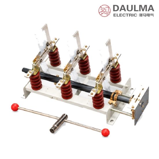
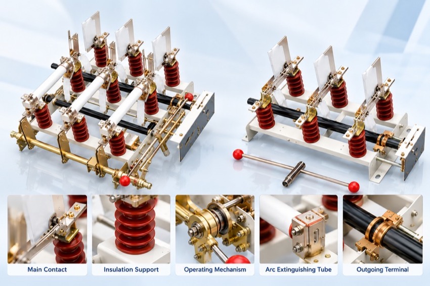
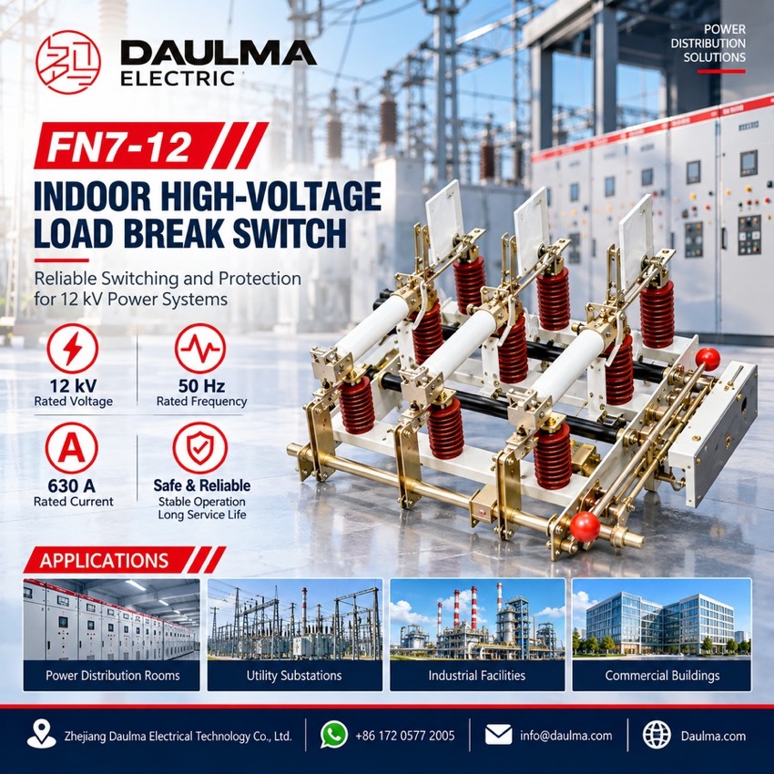
The FN7-12 is an indoor air-insulated load break switch for three-phase 50 Hz systems at 12 kV. It makes and breaks normal load current and closes onto short-circuit current; in the fused FN7-12R form the load switch – fuse combination unit interrupts any current up to and including short-circuit current, giving reliable protection for distribution transformers and cable feeders. Nine standard configurations share one base frame, combining incoming- or outgoing-side earthing switches, mechanical interlocking, striker-fuse tripping and a motorised opening device, so the same series covers line load switching and transformer-feeder protection.
Product Display
Model Designation
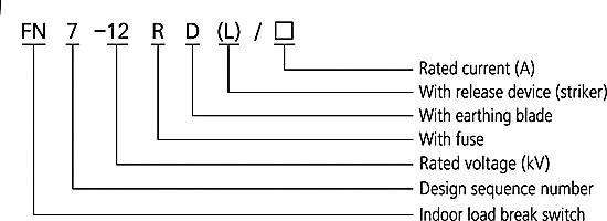
Model format: FN 7-12 R D (L)/□
- FN – indoor high-voltage load switch
- 7 – design sequence number
- 12 – rated voltage, kV
- R – with current-limiting fuses (combination unit)
- D – with trip device (striker)
- (L) – with earthing switch
- □ – rated current, A
- Example: FN7-12DR/630 is a 12 kV fused unit with striker trip at 630 A
Service Conditions
- Ambient temperature: +40 ℃ upper limit, -25 ℃ lower limit
- Altitude: not above 1000 m
- Relative humidity: daily average ≤ 95%, monthly average ≤ 90%
- Environment free from corrosive or flammable gases, vapour or obvious pollution
- No frequent violent vibration
Construction
Air-insulated open construction: live parts, blades and current-limiting fuses are mounted on a common 770 mm steel frame, and the visible isolating gap is rated 48 kV for 1 min power frequency and 85 kV lightning impulse, so one unit serves as both switch and isolator within its rating.
The on-frame CS6 manual mechanism gives simple, reliable make and break action with low maintenance and needs about 1200 mm of handle clearance. On striker-fuse (RA) versions the fuse striker opens the affected pole after a fault, the L interlocking device enforces the correct sequence between switch and earthing switch, and the F motorised opening device permits remote or automatic tripping.
Technical Data
| No. | Item | Unit | 400 A version | 630 A version |
|---|---|---|---|---|
| 1 | Rated voltage | kV | 12 | 12 |
| 2 | Rated frequency | Hz | 50 | 50 |
| 3 | Rated current | A | 400 | 630 |
| 4 | 1 min power-frequency withstand voltage (phase-to-phase / to earth) | kV | 42 | 42 |
| 5 | 1 min power-frequency withstand voltage (isolating gap) | kV | 48 | 48 |
| 6 | Lightning impulse withstand voltage (phase-to-phase / to earth) | kV | 75 | 75 |
| 7 | Lightning impulse withstand voltage (isolating gap) | kV | 85 | 85 |
| 8 | Rated short-time withstand current (4 s) | kA | 12.5 | 20 |
| 9 | Rated peak withstand current | kA | 31.5 | 50 |
| 10 | Rated short-circuit making current (peak) | kA | 31.5 | 50 |
Standards
The source datasheet quotes no specific product standard for the FN7-12 series. The switch is supplied to the manufacturer’s works specification and the agreed technical requirements, with routine and type tests on the main circuit and the isolating gap, and fuse coordination checked against the selected current-limiting fuse.
Installation & Dimensions
Installation Diagram
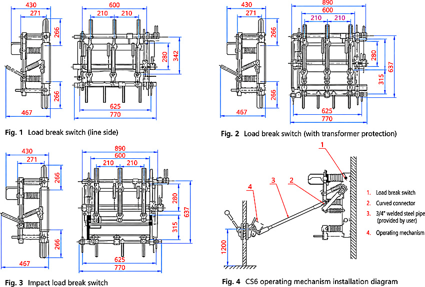
The FN7-12 is a fixed-mounted indoor switch installed on a wall or panel frame with the steel frame reliably earthed. Connect the incoming and outgoing cables to the terminals, fit the fuse cartridges on R and RA versions and refit the enclosing barrier. The CS6 mechanism uses a user-supplied 3/4-inch welded steel pipe extension rod with about 1200 mm of clearance, and the earthing switch and interlocking must be checked before commissioning.
| Outline dimension | Value (mm) |
|---|---|
| Base frame overall width (all versions) | 770 |
| Upper structure width, line-side version | 600 |
| Upper structure width, fused versions | 890 |
| Base mounting hole span | 625 |
| Phase spacing | 210 + 210 |
| Depth, upper section / overall | 430 / 467 |
| Overall height, line-side version | 342 |
| Overall height, fused versions | 637 |
| Support insulator section height (upper + lower) | 266 + 266 |
| Operating mechanism installation height | 1200 |