Aperçu du produit
Définition fonctionnelle
The JLSZW-6 and JLSZW-10 series Three-Phase Dry-Type Transformateur combiné are integrated electromagnetic mesurage devices designed for accurate voltage and current measurement in pour extérieur medium-voltage AC distribution systèmes. These units combine voltage transformation and current measurement functions in a single compact assembly, providing galvanically isolated secondary signals for comptage d’énergie, monitoring, and supervisory control applications.
Caractéristiques principales
| Article | Spécification (per order / nameplate) |
|---|---|
| Classe de tension système | 6 kV class (JLSZW-6) / 10 kV class (JLSZW-10) pour extérieur distribution applications |
| Fréquence assignée | 50 Hz (60 Hz available upon request) |
| VT configuration | Two single-phase fully-insulated transformateurs de tension in V/V three-phase connection |
| CT configuration | Two transformateurs de courant installed on phase A and phase C |
| VT rated secondary voltage | 100 V (line-to-line) |
| VT rated secondary output | Class 0.2: 2 × 15 VA; Class 0.5: 2 × 30 VA |
| CT courant secondaire assigné | 5 A, 2 A, or 1 A (as specified) |
| CT classes de précision | Mesurage and/or protection noyaus as specified (e.g., 0.2, 0.2S, 0.5) |
| Niveau d’isolement (JLSZW-10) | 12/42/75 kV (Um/Up/Ud) |
| Minimum creepage distance (JLSZW-10) | 440 mm |
| Enclosure construction | High-quality aging-resistant insulating material with résine époxy vacuum casting |
| Secondary winding features | Tapped secondary enroulements for enhanced mesurage accuracy |
| Normes applicables | IEC 61869-3 / IEC 61869-2; GB/T 20840.3 / 20840.2; GB 1207; GB 1208 |
| Application environment | Pour extérieur installation (urban/rural grids, industrial distribution, substations) |
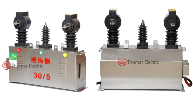
Product Show
 Thomas Electric")
Principe de fonctionnement
Transformateur de tension (TT) (VT) Operation: The transformateurs de tension operate on electromagnetic induction principles, stepping down high-voltage primary signals to standardized 100V secondary output. Two single-phase VTs are connected in V/V (open-delta) configuration to provide three-phase voltage measurement capability with reduced component count and installation footprint.
Transformateur de courant (TC) (CT) Operation: Operating on Faraday’s law of electromagnetic induction, the transformateurs de courant feature toroidal magnetic noyaus with conducteur primaire passing through the aperture and secondary enroulements wound around the noyau. The magnetic flux generated by primary current induces proportional voltage in the secondary winding, delivering standardized output current through connected burden. CTs are installed on phase A and phase C conductors.
Combined Integration: The integrated design provides simultaneous voltage and current measurement in a single enclosure, optimizing footprint and simplifying pour extérieur substation installations.
Position d’application système
- Pour extérieur Distribution Networks: 6-10kV overhead line terminals and pour extérieur switchgear
- Comptage d’énergie: Revenue-grade electricity measurement systèmes for utility billing
- Rural Electrification: Compact mesurage solutions for distributed grid infrastructure
- Industrial Power Distribution: Factory and facility pour extérieur transformer stations
- Intégration SCADA: Voltage and current data acquisition for supervisory control systèmes
Aperçu structurel
Epoxy resin vacuum-cast construction with fully-enclosed design ensures superior isolation performance, moisture resistance, environmental durability, and mechanical strength for long-term pour extérieur service. The high-quality aging-resistant enclosure material provides excellent anti-pollution capability and resistance to UV degradation, salt spray, and environmental contaminants. The integrated mounting configuration reduces installation complexity and provides compact footprint in pour extérieur substations and pole-mounted applications.
Désignation du modèle
 Thomas Electric")
Model Explication du code
- J — Voltage transformer (VT) function included
- L — Current transformer (CT) function included
- S — Three-phase configuration
- Z — Support (pillar) type mounting structure
- W — Pour extérieur installation type
- 6 / 10 — Voltage class (kV)
Model Explication du code
The JLSZW series designates a combined transformateur de mesure integrating voltage measurement and current measurement functions in a single pour extérieur-rated assembly. The “JL” prefix indicates the inclusion of both transformateur de tension (tt) (J) and transformateur de courant (tc) (L) functions. The “S” indicates three-phase capability achieved through V/V transformateur de tension (tt) connection and dual-phase transformateur de courant (tc) installation.
Conditions de service
The JLSZW-6 and JLSZW-10 series combined transformateurs de mesure are designed for pour extérieur operation under normal conditions de service in medium-voltage power distribution systèmes.
- Environnement d’installation: Pour extérieur installation with weather-resistant enclosure
- Altitude: Not exceeding 1000 m above sea level (higher altitude applications shall be specified for engineering confirmation and altitude correction factors)
- Température ambiante: −25 °C to +40 °C (pour extérieur rating)
- Humidité relative: Daily average ≤ 95%, monthly average ≤ 90% (condensation conditions acceptable with proper enclosure sealing)
- Conditions environnementales: Suitable for pour extérieur exposure including rain, wind, solar radiation, and atmospheric pollution; pollution severity level designation per IEC 60815 where specified
- Seismic conditions: Standard design for seismic intensity ≤ 7 degrees (higher seismic ratings available upon request)
Construction
Conception de construction
- VT Structure: Two single-phase fully-insulated transformateurs de tension in V/V connection
- CT Structure: Two transformateurs de courant on phase A and phase C conductors
- Isolation Système: Epoxy resin vacuum-cast fully-enclosed construction
- Enclosure Material: High-quality aging-resistant insulating material
- Secondary Enroulements: Tapped winding design for enhanced mesurage accuracy
- Mounting: Support-type structure for pole or platform mounting
The résine époxy vacuum casting process provides void-free isolation with stable dielectric properties and resistance to moisture ingress, environmental contamination, thermal cycling, and UV degradation for long-term pour extérieur service. The aging-resistant enclosure material ensures dimensional stability and mechanical integrity under pour extérieur exposure conditions.
Enroulements & Terminal Marking
Transformateur de tension (TT) Terminals:
- Bornes primaires (per VT unit): A/X or B/Y designation per phase assignment
- Bornes secondaires (per VT unit): a/x or b/y designation per phase assignment
- Output voltage (three-phase): 100 V line-to-line in V/V configuration
Transformateur de courant (TC) Terminals:
- Bornes primaires (phase A CT): P1 / P2
- Bornes secondaires (phase A CT): S1 / S2
- Bornes primaires (phase C CT): P1 / P2
- Bornes secondaires (phase C CT): S1 / S2
Terminal markings follow standard polarity conventions per IEC 61869 and GB normes. Correct terminal identification shall be observed to ensure mesurage accuracy and protection performance. Factory-provided terminal diagrams specify exact connection points for field installation.
Données techniques
This section provides selection-oriented données techniques for the JLSZW-6 and JLSZW-10 series three-phase pour extérieur combined transformateurs de mesure used in 6 kV and 10 kV class AC systèmes (50 Hz). Data shown below is intended for preliminary selection of voltage ratio, current ratio, classe de précision combinations, and charge assignées.
Definitions: VT rated secondary output indicates available burden capacity for voltage measurement circuits. CT classe de précision combination indicates available mesurage/protection noyaus per CT unit. Charge assignée (VA) is specified per secondary noyau. Ith is the rated courant thermique de courte durée (typically 1 s). Idyn is the courant dynamique assigné (peak).
Notation: Technical data is provided in nameplate format and verified by factory test report. Custom configurations for specific project requirements shall be confirmed by technical agreement prior to production release.
PTs Parameters
| Parameter | Spécification |
|---|---|
| Rated primary voltage | 10 kV / √3 (per VT unit in V/V connection) |
| Rated secondary voltage | 100 V / √3 (per VT unit) → 100 V line-to-line output |
| Accuracy class 0.2 | Rated output: 2 × 15 VA (per VT unit) |
| Accuracy class 0.5 | Rated output: 2 × 30 VA (per VT unit) |
| Niveau d’isolement | 12/42/75 kV (Um/Up/Ud) |
| Minimum creepage distance | 440 mm |
CTs Parameters
| Rated Primary Current (A) |
Rated Secondary Current |
Accuracy Class (Examples) |
Rated Burden (VA) |
|---|---|---|---|
| 5 to 600 | 5 A | 0.2, 0.2S, 0.5 | 2.5, 5, 10, 15 (as specified) |
| 10 to 600 | 2 A | 0.2, 0.2S, 0.5 | 2.5, 5, 10 (as specified) |
| 10 to 600 | 1 A | 0.2, 0.2S, 0.5 | 1.25, 2.5, 5 (as specified) |
Normes & Normative References
| Standard | Titre | Application |
|---|---|---|
| IEC 61869-1 | Transformateurs de mesure – Partie 1: Exigences générales | Exigences générales for both VT and CT |
| IEC 61869-2 | Transformateurs de mesure – Partie 2: Exigences supplémentaires pour transformateurs de courant | CT-specific requirements |
| IEC 61869-3 | Transformateurs de mesure – Part 3: Exigences supplémentaires for Inductive Transformateurs de tension | VT-specific requirements |
| GB/T 20840.1 | Transformateurs de mesure – Partie 1: Exigences générales | Norme nationale (aligned with IEC 61869 framework) |
| GB/T 20840.2 | Transformateurs de mesure – Partie 2: Transformateurs de courant | National CT requirements |
| GB/T 20840.3 | Transformateurs de mesure – Part 3: Transformateurs de tension | National VT requirements |
| GB 1207 | Electromagnetic Transformateurs de tension | National VT standard where specified by the project |
| GB 1208 | Transformateurs de courant | National CT standard where specified by the project |
| IEC 60815 | Selection and Dimensioning of High-Voltage Insulators for Polluted Conditions | Pour extérieur isolation coordination and pollution performance |
| IEC 60068-2-17 | Tests environnementaux – Brouillard salin | Optionnel (coastal environnement d’installational validation) |
Conformité aux tests d’usine
- VT tests de routine per applicable IEC/GB requirements (including polarity/marking, vérification du rapport, and vérification de la précision per specified class and burden)
- CT tests de routine per applicable IEC/GB requirements (including polarity/marking, vérification du rapport, and vérification de la précision per specified class and burden)
- Tests diélectriques per isolation coordination requirements and applicable standard
- Test de décharge partielle where specified by the project requirement
- Environmental tests including temperature rise, moisture resistance, and pollution testing where specified
- Inspection visuelle et dimensionnelle including marking and workmanship conformity
- Tests de type et spéciaux as required by the project spécification
Installation & Dimensions
 Thomas Electric")
- Outline dimensions and mounting details are provided in factory-supplied dimensional drawings specific to ordered configuration.
- The transformateur combiné shall be securely mounted using the designated fixing provisions suitable for pole or platform mounting.
- Connexion du conducteur primaire shall be made via overhead line terminals, busbar, or bolted connectors, depending on the installation configuration.
- Dégagement adéquat shall be maintained for isolation électrique, heat dissipation, maintenance access, and live-line working safety distances.
- Grounding provisions shall be implemented per normes applicables and local utility requirements.
- Lightning arrester coordination may be required per système protection coordination studies.
Notes de sécurité
- VT circuit secondaire must be properly fused per mesurage circuit protection requirements.
- CT circuit secondaire must never be left open when the transformer is energized, as dangerous high voltage may appear across the bornes secondaires.
- Pendant l’inspection or maintenance, the CT circuit secondaire shall be short-circuited before disconnecting any instruments.
- Un point of the VT circuit secondaire and un point of each CT circuit secondaire should be reliably grounded in accordance with normes applicables.
- Toute installation and maintenance work shall comply with local electrical safety regulations and utility operating procedures.
- Pour extérieur installations shall include appropriate barriers or safety signage per local requirements.
Informations de commande
Lors de la commande, the required configuration shall be specified according to the local grid requirements, normes applicables, and project technical spécification. The following parameters shall be clearly stated for technical confirmation and production release:
Transformateur de tension (TT) Spécification
- Rated primary voltage / transformation ratio
- Rated secondary voltage (typically 100 V for three-phase output)
- Accuracy class and charge assignée (e.g., Class 0.2 at 2 × 15 VA; Class 0.5 at 2 × 30 VA)
Transformateur de courant (TC) Spécification
- Courant primaire assigné / transformation ratio
- Courant secondaire assigné (5 A, 2 A, or 1 A)
- Accuracy class and charge assignée (VA) for each secondary noyau/winding
- Exigences de tenue au court-circuit: Ith (1 s) and Idyn (peak) where applicable
Environmental and Installation Spécification
- Niveau d’isolement and pollution severity per environnement d’installation
- Altitude and température ambiante range if outside standard conditions de service
- Mounting configuration (pole mounting, platform mounting, enclosure dimensions)
- Special requirements such as custom phase spacing (e.g., 340 mm), enclosure material selection, or specific terminal arrangements
Guide de sélection
Step 1: Determine rated primary voltage for VT based on système nominal voltage and isolation coordination requirements.
Step 2: Déterminer le courant primaire assigné for CT based on feeder/load rating and expected operating range.
Step 3: Sélectionner le mesurage accuracy requirements for both VT and CT (e.g., Class 0.2, 0.2S, or 0.5 for revenue mesurage).
Step 4: Confirmer la charge assignée (VA) for each circuit secondaire based on connected meters/relays and wiring losses.
Step 5: Verify niveau d’isolement and creepage distance requirements against environmental pollution severity and altitude.
Step 6: Verify CT tenue au court-circuit capability (Ith/Idyn) against the distribution système fault level where applicable.
If local utility or project requirements apply (e.g., specific niveau d’isolements, seismic ratings, terminal arrangement, mounting constraints, documentation language, or required certificates), specify them at the ordering stage. Custom configurations including enclosure dimensions, phase spacing, and specialized accuracy/burden combinations shall be confirmed by technical agreement and final data sheet prior to production.