Product Overview
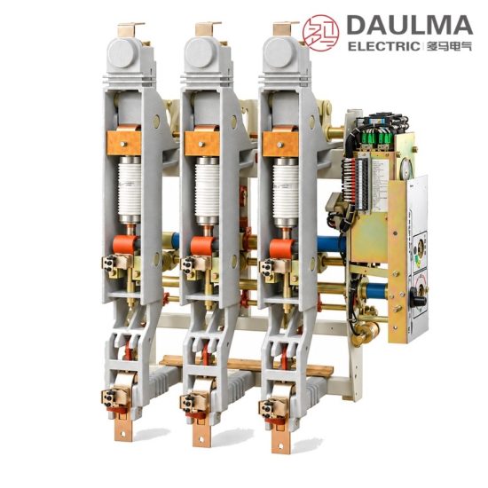
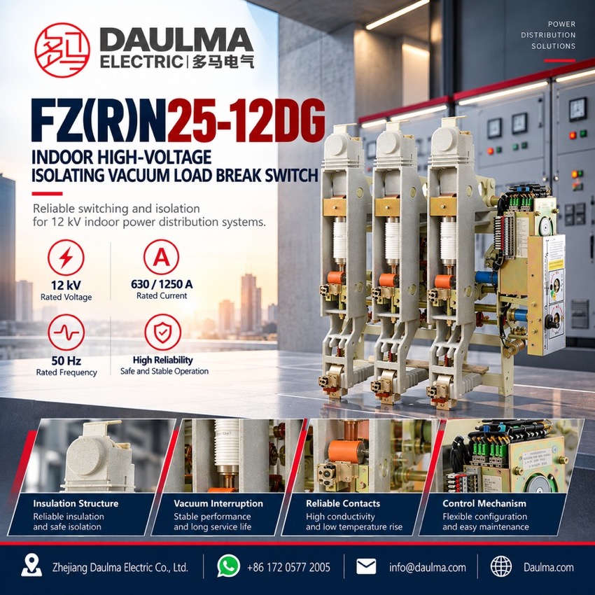
The FZN25-12DG indoor high-voltage vacuum load break switch is a three-phase 50 Hz, 12 kV switching unit that combines the load break switch, the isolating switch and the earthing switch on one frame. It is built to GB 3804 for AC load break switches and GB 16926 for switch-fuse combination units, and serves as the incoming, sectionalizing and transformer-protection unit of 12 kV metal-enclosed and air-insulated switchgear. Two rated currents are offered, 630 A and 1250 A, both with 25 kA short-time withstand current and a spring energy-storage mechanism. In the FZRN25-12DG combination unit the circuit is completed with back-up fuses that clear short-circuit current, so the switch itself only makes and breaks load current.
Product Display
Model Designation
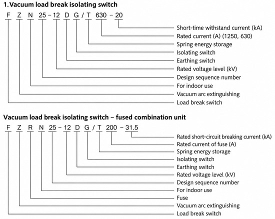
Model format: FZN25-12DG/T 630-25 or 1250-25 (load break switch) and FZRN25-12DG/T 200-31.5 (combination unit)
- F: load break switch; Z: vacuum; N: indoor type
- 25: design sequence number; 12: rated voltage, kV
- D: with earthing switch; G: with isolating switch; T: spring energy-storage mechanism
- 630 / 1250: rated current, A; 25: rated short-time withstand current, kA
- R: combined with fuse; 200: rated current of the fuse, A; 31.5: rated short-circuit breaking current, kA
- D and G are ordered separately when only one of the two switches is required; a 125 A fuse is available for lower-rated feeders
Service Conditions
- Ambient temperature: +40 °C upper, -10 °C lower
- Altitude: not more than 1000 m
- Relative humidity: daily average not more than 95%, monthly average not more than 90%
- Vapour pressure: daily average ≤ 2.2 × 10⁻³ MPa, monthly average ≤ 1.8 × 10⁻³ MPa
- Seismic intensity: not more than 8 degrees
- Site condition: indoor installation with no dripping, no fire or explosion hazard, no chemical corrosive gas and no violent vibration
Construction
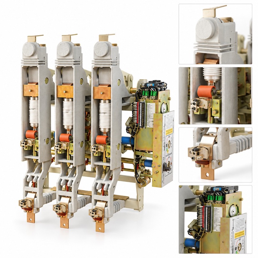
The three poles are carried on a common metal frame, with the vacuum interrupters and the isolating and earthing switches supported on insulator bases and joined by flexible connections. Controls, position indication and the mechanism are grouped on the front operating panel, so all three switch positions can be operated and verified from the cubicle front.
In the combination unit the fuse is held between upper and lower clips and acts on the pole through a trip plate, so a blown fuse trips the switch and reports the loss of a phase. The isolating switch provides the maintenance break and the earthing switch bonds the de-energised side.
Technical Data
| No. | Item | Unit | FZN25-12DG/T 630-25 | FZN25-12DG/T 1250-25 | FZRN25-12DG/T 200-31.5 |
|---|---|---|---|---|---|
| 1 | Rated voltage | kV | 12 | 12 | 12 |
| 2 | Rated frequency | Hz | 50 | 50 | 50 |
| 3 | Rated current | A | 630 | 1250 | 200 (fuse) |
| 4 | Rated short-time withstand current | kA | 25 | 25 | 25 |
| 5 | Rated peak withstand current | kA | 63 | 63 | 63 |
| 6 | Rated short-circuit making current | kA | 63 | 63 | — |
| 7 | Rated active load breaking current | A | 1250 | 1250 | 1250 |
| 8 | Rated closed-loop breaking current | A | 1250 | 1250 | 1250 |
| 9 | No-load transformer breaking capacity | kVA | 2000 | 2000 | 2000 |
| 10 | Earth fault current | A | 20 | 20 | 20 |
| 11 | Line and cable charging current under earth fault | A | 20 | 20 | 20 |
| 12 | Rated short-circuit breaking current | kA | — | — | 31.5 or 50 (by fuse) |
| 13 | Rated transfer current | A | 3150 | 3150 | 3150 |
| 14 | Inherent opening time | ms | 45 | 45 | 45 |
| 15 | 1 min power-frequency withstand voltage (phase and earth, vacuum gap / isolating gap) | kV | 42/48 | 42/48 | 42/48 |
| 16 | Lightning impulse withstand voltage (phase and earth, vacuum gap / isolating gap) | kV | 75/85 | 75/85 | 75/85 |
| 17 | Mechanical life | operations | > 10000 | > 10000 | > 10000 |
Standards
The design follows GB 3804 for AC high-voltage load break switches (3.6 kV to 40.5 kV), GB 16926 for high-voltage load break switch-fuse combination units, and IEC 60265 and IEC 60420 for indoor switch-disconnectors and switch-fuse combinations.
Installation & Dimensions
Installation Diagram
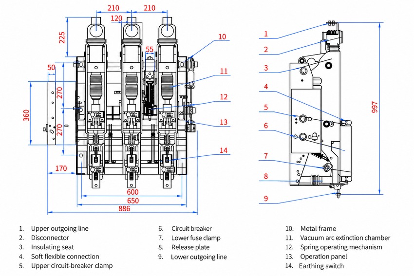
The three-pole unit is bolted into the cubicle frame across an overall width of 886 mm, with a 650 mm mounting envelope, 600 mm between fixing centres, 210 mm phase spacing and an overall height of 997 mm. Charge the spring, confirm the closed, open and earthed positions on all three poles, verify the interlocking between load break switch, isolating switch and earthing switch, and on the combination unit fit the specified fuse between the upper and lower clips and confirm the trip plate engagement. Before energisation, carry out the 1 min power-frequency withstand test at 42 kV on the main circuit and 48 kV across the isolating gap, and bond the frame to the earth network of the switchgear.
| Dimension | Value (mm) |
|---|---|
| Overall width | 886 |
| Mounting envelope | 650 |
| Fixing centres | 600 |
| Phase spacing | 210 |
| Overall height | 997 |