Product Overview
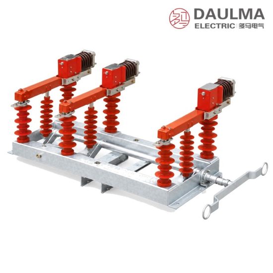
The FZW32-12/630-20 is an outdoor three-pole vacuum load break switch for 50 Hz, 12 kV distribution networks. Vacuum interrupters take over the breaking duty while the isolating knives leave a clearly visible open gap, so one unit performs both load switching and sectioning on the pole. Fitted with a spring or motor operating mechanism and a controller, the switch also serves as a sectionalizing device or an automatic line divider on urban and rural overhead feeders.
Product Display
Model Designation
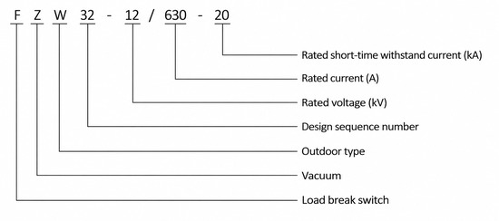
Model format: FZW32-12/T 630-20 (also written FZW32-12/630-20)
- F – load break switch
- Z – vacuum
- W – outdoor type
- 32 – design sequence number
- 12 – rated voltage, kV
- T – spring operating mechanism
- 630 – rated current, A
- 20 – rated short-time withstand current, kA
- Optional suffix behind the mechanism symbol – control arrangement (manual spring, motorised, or controller for automatic line division)
Service Conditions
- Ambient temperature: +40 ℃ maximum, -40 ℃ minimum
- Altitude: not more than 1000 m; higher sites require a correspondingly higher insulation level
- Wind pressure: not more than 700 Pa, equivalent to a wind speed of 34 m/s
- Seismic intensity: not more than 8 degrees
- Pollution level: IV
- Maximum daily temperature difference: not more than 25 K
- Relative humidity: daily average ≤ 95%, monthly average ≤ 90%
- No flammable gas, explosion risk, chemical corrosion or severe vibration
Construction
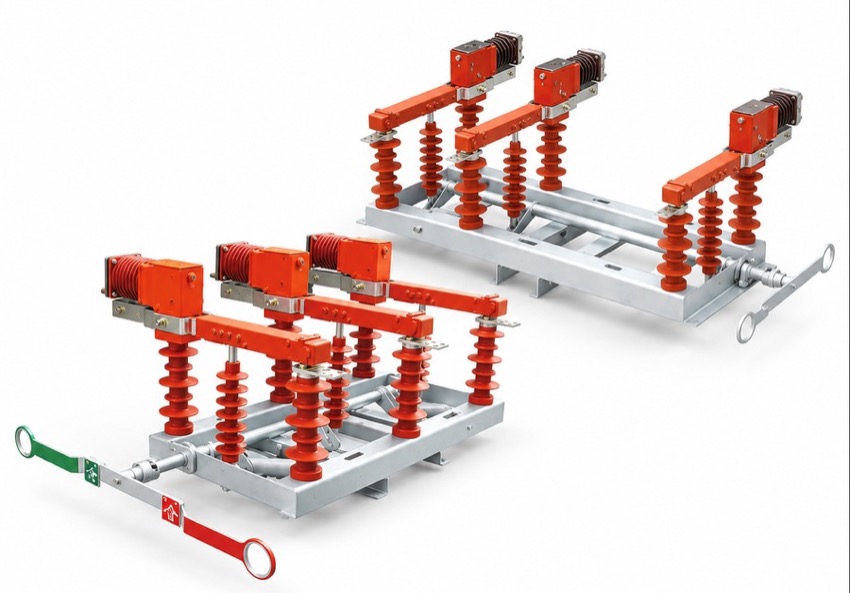
The three poles are mounted on a common steel frame, each pole combining a vacuum interrupter with an isolating knife on porcelain composite columns for outdoor duty at pollution level IV. The isolating knives are driven by a spring-over-centre mechanism with three-pole ganged operation, which fixes the opening simultaneity of the interrupters at the factory.
A quick-acting mechanism sets the interrupter travel speed independently of the operator, so arcing time does not depend on how fast the handle is moved. In service the switch makes and breaks rated load current, closed-loop transfer current, cable charging current and capacitor bank current, while short-circuit current is cleared by back-up fuses or upstream protection.
Technical Data
| No. | Item | Unit | Parameter |
|---|---|---|---|
| 1 | Rated voltage | kV | 12 |
| 2 | Rated frequency | Hz | 50 |
| 3 | Rated current | A | 630 |
| 4 | Rated active load breaking current | A | 630 |
| 5 | Rated closed-loop breaking current | A | 630 |
| 6 | 5% rated active load breaking current | A | 31.5 |
| 7 | Rated cable charging breaking current | A | 10 |
| 8 | Rated capacitor bank breaking current | A | 100 |
| 9 | 1 min power-frequency withstand voltage (vacuum gap / phase and earth / isolating gap) | kV | 42/48 |
| 10 | Lightning impulse withstand voltage (phase and earth / isolating gap) | kV | 75/85 |
| 11 | Rated short-time withstand current | kA | 20 |
| 12 | Rated short-circuit duration | s | 4 |
| 13 | Rated peak withstand current | kA | 50 |
| 14 | Rated short-circuit making current | kA | 50 |
| 15 | Mechanical life | operations | 10000 |
| 16 | Three-pole opening and closing simultaneity | ms | ≤ 5 |
Standards
Performance conforms to GB 3804, AC high-voltage load break switches for 3.6 kV to 40.5 kV, and to the applicable IEC recommendations for outdoor AC switching devices used on distribution networks. Full type tests and long-running service experience support the ratings given in the technical table.
Installation & Dimensions
Installation Diagram
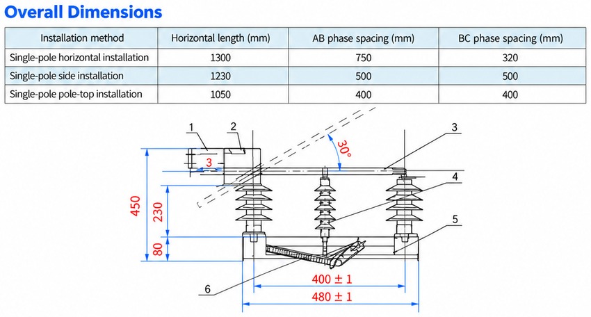
Choose the mounting mode and prepare the matching hardware: side mounting uses the lead wire terminal, pole, long and short support brackets, cable outlet and power supply cable, while horizontal and pole-top mounting use the switch support component, support arm, terminal, shaped pull rod and end cable. Level the frame before torquing the clamps, then charge the spring by hand, confirm close, open and trip actions, check the open-gap indication on all three poles and verify that three-pole simultaneity stays within 5 ms. Before energisation carry out the 1 min power-frequency withstand test on the main circuit, bond the frame to the earth network and re-check terminal clearances against the approved outline drawing. A potential transformer supplies the electric operating mechanism where motorised operation is ordered.
| Mounting mode | Overall width (mm) | Phase spacing (mm) |
|---|---|---|
| Horizontal pole mounting | 1300 | 750 + 320 |
| Side mounting | 1230 | 500 + 500 |
| Pole-top mounting | 1050 | 400 + 400 |