Article Content
High-Performance 11kV Cast-Resin Current Transformer ZW-10 for Metering & Protection per IEC 61869-2
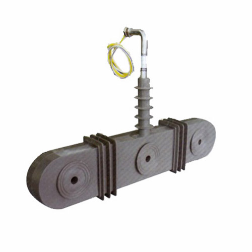
Introduction to the ZW-10 Current Transformer
The ZW-10 is a high-reliability, cast-resin insulated current transformer (CT) engineered for accurate current measurement and robust protective relay coordination in medium-voltage power systems operating at 11kV (IEC standard) or 10kV (domestic Chinese system). Designed in strict accordance with IEC 61869-2 and GB/T 20840.2, this instrument transformer leverages advanced vacuum pressure impregnation (VPI) epoxy resin technology to deliver superior dielectric strength, environmental resilience, and long-term operational stability.
Operating Principle of Cast-Resin Insulation
Cast-resin insulation in the ZW-10 employs a thermosetting epoxy resin system that fully encapsulates the primary conductor and secondary winding assembly under vacuum and pressure. This VPI process eliminates air voids and moisture ingress pathways, ensuring uniform dielectric properties throughout the insulation matrix. The cured resin exhibits excellent tracking resistance (compliant with IEC 60587), high mechanical strength, and thermal stability up to 130°C continuous operation. Unlike oil-filled alternatives, the solid insulation eliminates fire hazards, reduces maintenance overhead, and enables safe indoor or outdoor deployment without containment requirements. The resin’s coefficient of thermal expansion closely matches that of copper and silicon steel, minimizing stress-induced microcracks during thermal cycling—a critical factor for transformers subjected to daily load variations in distribution networks.
Advantages Over Oil-Immersed Designs
The ZW-10’s cast-resin construction offers distinct technical advantages over traditional oil-immersed CTs. First, it eliminates the risk of oil leakage, which can compromise insulation integrity and pose environmental contamination hazards—particularly critical in urban substations or indoor switchgear installations. Second, the solid dielectric provides higher short-circuit withstand capability; the ZW-10 is rated for 20kA/1s thermal short-circuit current and 50kA peak dynamic current, exceeding typical oil-CT performance at this voltage class. Third, the absence of liquid insulation simplifies transportation and installation logistics, as no oil sampling, degassing, or level monitoring is required. Finally, the compact physical footprint—enabled by higher dielectric strength of epoxy resin (≥20 kV/mm)—allows for space-efficient integration into ring main units (RMUs) and compact secondary substations, where spatial constraints are common.
Typical Applications Overview
The ZW-10 is primarily deployed in 11kV/10kV distribution substations requiring dual functionality: precision metering for billing and energy management, and high-fidelity current replication for protective relaying. Its dual-core design (typically one 0.2S/0.5 accuracy class core for metering and one 5P10/5P20 core for protection) ensures simultaneous compliance with metrological and protection standards. Common use cases include utility-owned primary substations feeding industrial parks, commercial building service entrances, renewable energy interconnection points (e.g., solar farms with 11kV export), and rural distribution feeders where reliability under harsh environmental conditions is paramount. The transformer’s IP54-rated terminal box and UV-stabilized resin formulation support extended outdoor service life even in coastal or high-pollution environments.
Technical Specifications
The ZW-10 current transformer is engineered to meet stringent electrical and environmental performance criteria essential for modern power systems. Below is a comprehensive specification table followed by detailed subsections on service conditions and dimensional parameters.
| Parameter | Value |
|---|---|
| Rated System Voltage (IEC) | 11 kV |
| Rated System Voltage (Domestic) | 10 kV |
| Rated Primary Current (Ip) | 50–3150 A (standard ratios); custom up to 4000 A |
| Rated Secondary Current (Is) | 1 A or 5 A |
| Metering Accuracy Class | 0.2S, 0.5S (per IEC 61869-2) |
| Protection Accuracy Class | 5P10, 5P15, 5P20 |
| Rated Output (Burden) | 5–30 VA (metering); 10–50 VA (protection) |
| Insulation Level (LI/AC) | 75 kV / 28 kV (1 min) |
| Short-Time Thermal Current | 20 kA for 1 s |
| Dynamic Withstand Current | 50 kA peak |
| Core Material | Grain-Oriented Electrical Steel (GOES), M4 grade |
| Insulation System | VPI Epoxy Resin, Class F (155°C) |
| Ambient Temperature Range | –40°C to +40°C |
| Altitude Limit | ≤1000 m above sea level (derating required above) |
Standard Service Conditions
The ZW-10 is rated for continuous operation under IEC 60060-defined standard service conditions: ambient temperature from –40°C to +40°C, relative humidity up to 95% non-condensing, and installation altitude not exceeding 1000 meters. At altitudes above 1000 m, the dielectric strength must be derated by 1% per 100 m increment due to reduced air density affecting external creepage performance. The transformer is suitable for both indoor switchgear compartments and outdoor pole- or pad-mounted substations, provided the terminal box remains sealed against dust and water ingress (IP54 minimum). In coastal or industrial atmospheres with high salt or chemical pollution, an optional hydrophobic silicone coating may be applied to the resin housing to enhance surface tracking resistance.
Electrical Performance Parameters
Key electrical tolerances are tightly controlled to ensure compliance with IEC 61869-2. For metering cores (0.2S class), current error must not exceed ±0.2% and phase displacement ≤±10 minutes at 100% rated current. Protection cores (5P20) must maintain composite error ≤5% at 20 times rated current under specified burden. The rated output (burden) is defined as the apparent power in volt-amperes (VA) that the CT can deliver to the connected secondary circuit while maintaining accuracy—typically 15 VA for metering and 30 VA for protection in standard configurations. Saturation characteristics are optimized via GOES core lamination thickness (0.23 mm) and precise air-gap control during winding assembly, ensuring linear response up to 20×In for protection applications.
Typical Applications
The ZW-10 current transformer serves as a foundational component in diverse medium-voltage infrastructure, delivering dual functionality for revenue-grade metering and fault-responsive protection.
Substation Secondary Metering
In utility-owned 11kV/0.4kV distribution substations, the ZW-10 provides the current input signal for tariff metering and SCADA telemetry. Installed on the 11kV feeder incomer or outgoing circuits, its 0.2S-class core interfaces with digital revenue meters compliant with IEC 62053-22. The high accuracy at low load currents (down to 1% of In) ensures precise energy accounting even during nighttime or weekend low-demand periods—critical for loss allocation and demand-side management. The cast-resin housing withstands electromagnetic interference from adjacent switchgear, preventing signal distortion in sensitive metering circuits.
Industrial Power Distribution
Large manufacturing facilities often operate their own 10kV internal distribution networks fed from a dedicated utility substation. Here, the ZW-10 monitors main incomer and motor feeder currents for both energy cost allocation and motor protection. Its 5P20 protection core drives overcurrent and earth-fault relays (e.g., IEC 60255-compliant devices) with sufficient saturation margin to avoid maloperation during motor starting inrush (typically 6–8×In for 5–10 seconds). The compact size allows retrofit into legacy switchboards without structural modifications, while the resin insulation resists chemical vapors common in petrochemical or pharmaceutical plants.
Renewable Energy Integration
Solar photovoltaic (PV) farms exporting power at 11kV require accurate export metering and anti-islanding protection. The ZW-10 is installed at the point of common coupling (PCC) to measure bidirectional energy flow. Its symmetrical core design ensures identical accuracy for both import and export directions, satisfying grid code requirements (e.g., ENTSO-E or local utility mandates). During grid faults, the protection core supplies fault current data to distance or differential relays within 20 ms, enabling rapid disconnection to maintain grid stability. The transformer’s wide temperature tolerance accommodates desert or alpine site conditions without performance degradation.
Rural and Suburban Distribution Networks
In remote or semi-urban areas, the ZW-10 supports automated feeder monitoring via integration with distribution automation terminals (DATs). Mounted on pole-top reclosers or sectionalizers, it provides real-time current data for fault location, isolation, and service restoration (FLISR) algorithms. The IP54 terminal box protects secondary connections from rain and dust, while the UV-resistant resin prevents embrittlement under prolonged solar exposure. With a design life exceeding 25 years, it reduces lifecycle costs in regions where access for maintenance is logistically challenging.
Commercial Building Service Entrances
High-rise office complexes or shopping malls with 10kV service entrances utilize the ZW-10 for tenant submetering and fire pump motor protection. The dual-core configuration allows separate metering for common-area lighting and HVAC versus individual tenant loads. The protection core ensures selective coordination with downstream molded-case circuit breakers (MCCBs), minimizing nuisance tripping during transient overloads. Indoor installation benefits from the transformer’s zero fire-risk profile, meeting stringent building codes such as NFPA 70 (NEC Article 450).
Compliance with International Standards
The ZW-10 current transformer is certified to IEC 61869-2:2012 (“Instrument transformers – Part 2: Additional requirements for current transformers”) and aligns with the Chinese national standard GB/T 20840.2-2014, which adopts IEC 61869-2 with minor national deviations.
IEC 61869-2 Compliance Details
IEC 61869-2 defines performance requirements for accuracy, insulation, temperature rise, and short-circuit withstand. The ZW-10 meets all mandatory clauses: accuracy verification per Clause 6.3 using calibrated test sets with uncertainty ≤0.05%; power-frequency withstand voltage of 28 kV RMS for 1 minute (Clause 7.2); partial discharge levels <10 pC at 1.2×Um/√3 (Clause 7.4); and temperature rise ≤60 K for windings under rated load (Clause 8). Type tests—including lightning impulse (75 kV peak, 1.2/50 μs waveform) and short-circuit force validation—are conducted at accredited laboratories and documented in the manufacturer’s test report.
GB/T 20840.2 Alignment and National Deviations
GB/T 20840.2 mirrors IEC 61869-2 but includes supplementary requirements for the Chinese market. Key additions include mandatory seismic testing (horizontal acceleration 0.2g, vertical 0.1g per GB/T 13540) and stricter partial discharge limits (<5 pC at 1.1×Um/√3) for transformers used in urban substations. The ZW-10 incorporates reinforced core clamping and resin anchoring to satisfy seismic demands without compromising magnetic performance. While IEC permits 5 A secondary current as default, GB/T emphasizes 1 A systems for new installations to reduce copper losses—hence the ZW-10 offers both options with identical accuracy envelopes.
Testing and Certification Requirements
Each production unit undergoes routine tests per IEC 61869-2 Clause 10: visual inspection, winding continuity, polarity verification, turns ratio check (±0.5% tolerance), and power-frequency withstand. Type-tested samples are revalidated every five years or after design changes. Certification is issued by CNAS-accredited bodies (e.g., CEPREI) and includes IECEx or CCC marks as applicable. For export markets, additional certifications (e.g., KEMA-KEUR, UL) may be obtained upon request, though the base design inherently satisfies global safety principles through its intrinsic insulation integrity and fault containment.
On-Site Testing Procedures
Post-installation verification ensures the ZW-10 performs within specifications under actual service conditions. The following tests should be conducted before energization.
Insulation Resistance Test
Using a 2500 V DC megohmmeter, measure insulation resistance between primary-to-secondary, primary-to-ground, and secondary-to-ground. Acceptance criterion: ≥1000 MΩ at 20°C. Correct for temperature using RT2 = RT1 × 2(T1–T2)/10. Low readings indicate moisture ingress or resin cracking—requiring drying or replacement. This test validates the integrity of the VPI resin barrier after transportation stresses.
Turns Ratio Test
Apply a low-voltage AC source (e.g., 120 V) to the primary and measure secondary voltage. Calculate actual ratio = Vp/Vs. Compare to nameplate ratio; deviation must be ≤±0.5% for metering cores and ≤±1.0% for protection cores. Use a dedicated ratio tester (e.g., Omicron CT Analyzer) for higher precision. Significant errors suggest winding shorts or incorrect tap selection.
Polarity Test
Verify reducing polarity per IEC 61869-2 Annex B: momentarily apply DC voltage to primary (P1 positive, P2 negative); observe secondary voltage spike direction with an analog voltmeter. The S1 terminal should show positive deflection. Incorrect polarity causes 180° phase shift, leading to watt-hour meter reversal or relay misoperation. Digital multimeters with min/max capture can also be used.
Power Frequency Withstand Voltage Test
Apply 28 kV RMS at 50 Hz between primary and grounded secondary/enclosure for 1 minute. Use a calibrated test transformer with overcurrent trip set at 5 mA. No flashover or breakdown should occur. This validates insulation integrity after handling and installation. For field testing, a reduced voltage (80% of factory test) may be acceptable per utility guidelines if full test equipment is unavailable.
Secondary Winding Resistance and Burden Verification
Measure DC resistance of secondary windings with a 4-wire milliohmmeter. Compare to factory baseline (±5% tolerance). Then, connect the actual burden (relays, meters, wiring) and verify total impedance does not exceed rated VA at rated current. Excessive burden causes saturation and accuracy loss—especially critical for 0.2S metering cores where burden >15 VA may degrade performance below 10% In.
Preventive Maintenance Guide
Although cast-resin CTs like the ZW-10 are largely maintenance-free, periodic inspections extend service life and prevent unexpected failures.
Annual Visual and Functional Inspection
Inspect annually for: (1) surface cracks or tracking on resin housing; (2) corrosion on primary terminals or grounding lugs; (3) loose secondary connections in the terminal box; (4) signs of overheating (discoloration, odor). Verify secondary circuit continuity and insulation resistance (>100 MΩ). Tighten terminal screws to 12 N·m torque using a calibrated wrench. Clean housing with mild detergent—avoid solvents that degrade resin.
Five-Year Comprehensive Maintenance
Every five years, perform: (1) full ratio and polarity retest; (2) partial discharge measurement if test equipment is available (acceptance: <20 pC at 1.2×Um/√3); (3) thermal imaging under 50%+ load to detect hot spots (>10 K above ambient indicates connection issues); (4) review of connected burden against original design. Replace gaskets on terminal box if hardened or cracked. Document all findings in the asset management system for trend analysis.
Fault Diagnosis and Troubleshooting
Common failure modes include open-circuited secondaries (causing dangerous overvoltages), core saturation due to excessive burden, and moisture ingress through compromised seals. Symptoms: erratic meter readings, relay false trips, or audible humming. If secondary opens during operation, de-energize immediately—the resulting high voltage can exceed 10 kV. Always short-circuit secondary terminals before disconnecting instruments. For suspected core damage, compare excitation curves to baseline; significant shift in knee-point voltage indicates degraded magnetic properties requiring replacement.
| Maintenance Interval | Activities |
|---|---|
| Annual | Visual inspection, IR scan, terminal torque check, insulation resistance |
| 5 Years | Ratio/polarity test, burden verification, PD test (if feasible), gasket replacement |
| After Fault | Full electrical retest, core excitation curve, mechanical integrity check |
Conclusion
The ZW-10 11kV cast-resin current transformer represents a technically mature solution for modern medium-voltage infrastructure, combining metrological precision with protective reliability in a single, environmentally robust package. Its compliance with IEC 61869-2 and GB/T 20840.2 ensures interoperability across global and domestic grids, while the VPI epoxy resin insulation system delivers unmatched safety, longevity, and resilience against environmental stressors. The use of high-permeability GOES core material guarantees low magnetizing current and minimal phase error—critical for both revenue metering and directional protection schemes. With a design life of 25–30 years under standard service conditions, the ZW-10 significantly reduces total cost of ownership compared to oil-filled alternatives, eliminating recurring maintenance tasks such as oil sampling, leak repairs, and fire mitigation measures. Its compact form factor facilitates integration into space-constrained switchgear, supporting the industry trend toward modular and prefabricated substations. Field-proven in diverse applications—from urban utility feeders to remote renewable sites—the ZW-10 consistently delivers the accuracy, durability, and safety demanded by today’s power systems engineers. When installed and maintained per the procedures outlined in this document, it provides decades of trouble-free service, forming a dependable cornerstone of substation instrumentation and protection architecture.