Article Content
CT-35K 33kV Cast-Resin Current Transformer for Substation Metering and Protection – IEC 61869-2 Certified
Introduction to the CT-35K Current Transformer
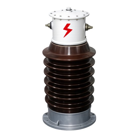
The CT-35K is a high-reliability, cast-resin insulated current transformer engineered for operation in 33 kV (IEC standard) or 35 kV (domestic system equivalent) electrical networks. Designed in strict compliance with IEC 61869-2 and GB/T 20840.2, this device serves dual roles in both revenue-grade metering and protective relaying applications. Its robust construction ensures long-term stability under demanding environmental and electrical stress conditions typical of medium-voltage substations.
Operating Principle of Cast-Resin Insulation
Cast-resin insulation in the CT-35K utilizes vacuum pressure impregnation (VPI) epoxy resin technology to encapsulate the primary conductor and secondary windings within a homogeneous, void-free dielectric matrix. This process eliminates air pockets that could lead to partial discharges under high electric fields. The resin formulation exhibits excellent thermal conductivity (0.2–0.3 W/m·K), enabling efficient heat dissipation during continuous operation at rated current. Dielectric strength exceeds 20 kV/mm, ensuring reliable performance even at the system’s maximum operating voltage of 36 kV (Um). Unlike oil-filled alternatives, the solid insulation provides immunity to leakage, fire hazards, and maintenance-intensive fluid management. The resin also demonstrates superior resistance to UV radiation, moisture ingress (IP54 rating), and tracking under polluted conditions—critical for outdoor installations in coastal or industrial zones.
Advantages Over Oil-Immersed Designs
Compared to traditional oil-immersed current transformers, the CT-35K offers significant operational and safety benefits. First, it eliminates flammability risks, making it suitable for indoor substations and confined urban installations where fire codes restrict hydrocarbon-based insulation. Second, its maintenance-free design reduces lifecycle costs: no oil sampling, degassing, or level monitoring is required. Third, the compact footprint—enabled by higher dielectric strength of epoxy versus mineral oil—facilitates retrofitting into existing switchgear bays with limited clearance. Mechanical robustness is enhanced through monolithic casting, which resists vibration-induced winding displacement during short-circuit events (withstanding up to 40 kA for 1 s). Additionally, the absence of breathing mechanisms prevents moisture absorption, ensuring stable dielectric properties over decades of service. These attributes align with modern grid reliability standards emphasizing passive safety and minimal intervention.
Typical Applications Overview
The CT-35K is deployed across diverse infrastructure segments requiring accurate current transformation at 33/35 kV. Primary use cases include utility-owned transmission substations for feeder metering and differential protection, industrial facilities with captive power plants needing harmonic-resilient sensing, and renewable energy interconnection points (e.g., solar farms) where DC offset immunity is critical. Its dual-core configuration—one core optimized for 0.2S class metering, another for 5P20 protection—enables simultaneous compliance with billing accuracy and fault detection requirements. In rural distribution networks, the CT-35K’s wide ambient temperature tolerance (-40°C to +55°C) ensures performance stability despite seasonal extremes.
Technical Specifications
The CT-35K adheres to precise engineering parameters defined by international and domestic standards, ensuring interoperability and predictable performance across global markets.
Rated Electrical Parameters
Key electrical ratings include a system voltage of 33 kV (IEC) / 35 kV (GB), with a highest voltage for equipment (Um) of 36 kV. Standard current ratios range from 50/1 A to 3000/5 A, configurable with multi-tap secondary windings for flexible scaling. Accuracy classes are designated as 0.2S for metering (per IEC 61869-2 Table 4) and 5P20 for protection (composite error ≤5% at 20× rated current). Rated burden is typically 15 VA per core, though options up to 30 VA are available for long cable runs. Short-time thermal current rating is 40 kA for 1 second, while dynamic withstand current reaches 100 kA peak. Insulation coordination follows IEC 60071-1: power frequency withstand voltage is 70 kV rms for 1 minute, and lightning impulse withstand voltage is 170 kV peak (1.2/50 μs waveform). Phase displacement at rated current is ≤±10 minutes for 0.2S class, ensuring minimal angular error in vector-based metering systems.
Environmental and Mechanical Ratings
The CT-35K operates reliably under standard service conditions per IEC 61869-2 Clause 5: ambient temperature range of -40°C to +55°C, relative humidity up to 100% (condensation permitted), and altitude ≤1000 m above sea level (derating applies above 1000 m per IEC 60664-1). For high-altitude sites (e.g., >2000 m), external creepage distance is increased to ≥25 mm/kV to prevent flashover. The housing is constructed from UV-stabilized cycloaliphatic epoxy resin with a smooth surface finish to minimize pollution accumulation. Mounting options include flange-type (M12 bolts, PCD 150 mm) or support rod configurations compatible with standard 33 kV post insulators. Secondary terminals are housed in an IP54-rated terminal box with screw-type connectors accepting 2.5–6 mm² stranded copper conductors. Weight is approximately 45 kg, facilitating manual handling during installation.
Core and Winding Construction
The magnetic circuit employs grain-oriented electrical steel (GOES) with a thickness of 0.23 mm and core loss ≤0.9 W/kg at 1.7 T, 50 Hz. This material minimizes hysteresis and eddy current losses, critical for maintaining accuracy under low-load conditions (down to 1% of rated current for 0.2S class). Secondary windings use enameled copper wire (Class H insulation, 180°C rating) wound with precision layering to control leakage reactance. Inter-turn insulation withstands 3 kV impulse testing. The primary conductor is a solid copper bar sized to carry continuous current without exceeding 65 K temperature rise above ambient. All internal components are fully embedded in VPI epoxy under vacuum (≤5 mbar) and cured at 120°C for 8 hours to achieve complete polymerization and eliminate microvoids.
Typical Applications
The CT-35K’s dual-core architecture and ruggedized design make it suitable for a broad spectrum of medium-voltage infrastructure scenarios.
Substation Secondary Metering
In utility transmission substations, the CT-35K’s 0.2S accuracy class enables compliance with ISO/IEC 17025 requirements for revenue metering. When paired with Class 0.2S kWh meters, the combined system uncertainty remains below ±0.5% over a 1–120% load range. This is essential for cross-border energy trading or large industrial consumers billed under time-of-use tariffs. The transformer’s low phase error (<±5 minutes at 5% In) ensures accurate reactive energy measurement, critical for power factor correction schemes. Installation typically occurs on 33 kV outgoing feeders, with secondary leads routed to metering cabinets via shielded twisted-pair cables to mitigate electromagnetic interference from adjacent switchgear operations.
Industrial Power Distribution
Heavy industries—such as steel mills, petrochemical plants, and data centers—deploy the CT-35K for both process monitoring and arc-flash mitigation. The 5P20 protection core reliably drives overcurrent relays (e.g., IEC 60255-compliant devices) during bolted faults, while the metering core feeds SCADA systems for real-time load profiling. In environments with high harmonic distortion (THD >15%), the GOES core’s low remanence prevents saturation during transient recovery, maintaining ratio accuracy. For example, in a 35 kV motor starter application, the CT-35K detects locked-rotor conditions within 20 ms, triggering breaker tripping before thermal damage occurs.
Renewable Energy Integration
Solar and wind farms connecting to 33 kV grids utilize the CT-35K for anti-islanding protection and export metering. During grid faults, the transformer must accurately replicate asymmetric currents containing DC offsets—a challenge addressed by the air-gapped core design in the protection winding, which increases linear range. At a 50 MW solar plant in Spain, CT-35K units enabled precise curtailment control during voltage sags, meeting ENTSO-E grid code requirements. The cast-resin housing resists salt fog corrosion in coastal sites, while the wide temperature range accommodates desert diurnal swings (e.g., -10°C nights to +50°C days).
Rural and Suburban Distribution Networks
In remote areas with limited maintenance access, the CT-35K’s hermetic sealing eliminates degradation from humidity or dust. Utilities in Southeast Asia deploy these units on pole-mounted 35 kV reclosers for automated sectionalizing. The 5P20 core ensures coordination with downstream fuses during tree-contact faults, minimizing outage scope. For agricultural cooperatives using prepaid metering, the 0.2S core provides tamper-resistant billing data even at light loads (e.g., irrigation pumps operating at 20% capacity). Creepage distance of 630 mm meets IEC 60815 pollution severity Level III, preventing flashovers during monsoon seasons.
Compliance with International Standards
The CT-35K is certified against globally recognized standards, ensuring interoperability and regulatory acceptance.
IEC 61869-2 Certification Details
Compliance with IEC 61869-2:2012 (“Instrument transformers – Part 2: Additional requirements for current transformers”) governs all performance aspects. Key verified parameters include: ratio error ≤±0.2% and phase displacement ≤±10′ for 0.2S class at 100% In; composite error ≤5% for 5P20 at 20× In; and knee-point voltage ≥150 V for protection cores (ensuring sufficient excitation margin during faults). Type tests per Clause 7 include temperature rise (≤60 K for windings), short-circuit withstand (40 kA/1s), and impulse voltage (170 kV peak). Routine tests (Clause 8) cover power frequency withstand (70 kV/1 min), partial discharge (<10 pC at 1.2 Um/√3), and polarity verification. The certification is issued by accredited laboratories (e.g., KEMA, CESI) with test reports traceable to SI units.
Alignment with GB/T 20840.2
For Chinese domestic markets, the CT-35K meets GB/T 20840.2-2014 (“Instrument transformers – Part 2: Current transformers”), which largely harmonizes with IEC 61869-2 but includes localized requirements. Notably, GB/T mandates a higher lightning impulse level (185 kV vs. 170 kV) for 35 kV class equipment and specifies stricter partial discharge limits (<5 pC at 1.2 Um/√3). The thermal short-circuit current rating is expressed as Ith²t ≥ 1600 kA²s (equivalent to 40 kA/1s). Additionally, GB/T requires flame retardancy testing per GB/T 5169.16 (V-0 rating), validated through vertical burning tests on resin samples. Documentation includes bilingual (Chinese/English) test certificates issued by CNAS-accredited labs.
Key Differences Between IEC and Domestic Standards
While IEC 61869-2 focuses on functional performance, GB/T 20840.2 emphasizes environmental resilience for China’s diverse climates. For instance, GB/T requires cold-impact testing at -40°C (vs. IEC’s -25°C baseline) and salt-spray resistance per GB/T 10125 (96-hour exposure). Marking requirements also differ: GB/T mandates Chinese characters for “Current Transformer” and rated parameters, whereas IEC permits English-only labeling. From a design perspective, the CT-35K incorporates a thicker resin wall (≥25 mm vs. 20 mm minimum per IEC) to satisfy GB/T’s enhanced mechanical strength criteria. Despite these variations, the core electromagnetic design remains identical, enabling single-platform manufacturing for global deployment.
On-Site Testing Procedures
Post-installation verification ensures the CT-35K performs within specified tolerances before energization.
Insulation Resistance Test
Conducted using a 5 kV DC megohmmeter between primary-to-ground, secondary-to-ground, and primary-to-secondary. Acceptance criterion: ≥10,000 MΩ at 20°C. Temperature correction follows IEEE 43 formula: Rcorr = Rmeas × 2(40-T)/10. Low readings indicate moisture ingress or resin cracking—requiring drying or replacement. Test duration is 1 minute after stabilization.
Turns Ratio Test
Performed with a dedicated CT analyzer (e.g., Omicron CT Analyzer) applying 1–5 A to the primary. Measured secondary current is compared to theoretical ratio. Tolerance: ±0.2% for 0.2S cores, ±1% for 5P20 cores. Deviations >0.5% warrant core demagnetization followed by retest. Open-circuit secondary voltage must not exceed 500 V during test to avoid insulation stress.
Polarity Test
Verifies reducing polarity (IEC 61869-2 Figure 3) using DC pulse method: momentary 6 V battery connection to primary (P1→P2) should yield positive deflection on secondary (S1→S2) via analog galvanometer. Digital testers display polarity symbol directly. Incorrect polarity causes 180° phase reversal, leading to relay misoperation or negative metering—requiring terminal swap.
Power Frequency Withstand Voltage Test
Primary-to-ground subjected to 70 kV rms, 50 Hz for 1 minute using HV test set. Secondary windings shorted and grounded. Leakage current must remain <1 mA. Partial discharge inception voltage (PDIV) is monitored; values <60 kV indicate voids. Test conducted at ≤80% humidity to avoid surface flashover.
Short-Circuit Test
Secondary windings short-circuited; primary injected with 10–20% rated current. Voltage drop across primary measured to calculate impedance. For 5P20 cores, knee-point voltage (Vk) must exceed 150 V (per IEC 61869-2 Annex B). Vk = (Iknee × Zm), where Zm is magnetizing impedance. Low Vk indicates core saturation risk during faults.
Preventive Maintenance Guide
Structured maintenance extends service life beyond 30 years while ensuring continued accuracy.
Periodic Inspection Protocol
Annual visual checks include: resin surface for cracks/UV degradation (use 10× magnifier), terminal tightness (torque: 2.5 N·m for M4 screws), and housing cleanliness (wipe with isopropyl alcohol if contaminated). Infrared thermography during peak load identifies hot spots (>10 K above ambient at connections). Secondary circuit continuity verified with multimeter (resistance <0.1 Ω). Any discoloration or tracking marks necessitate dielectric testing.
Maintenance Intervals and Fault Diagnosis
A 5-year schedule includes: insulation resistance retest, ratio verification, and partial discharge measurement (<20 pC at 1.2 Um/√3). Common faults: ratio drift (caused by core aging—remedied by recalibration), open secondary (tripped by broken wire—detected via loop resistance test), and moisture ingress (evidenced by <1000 MΩ insulation—requires oven drying at 80°C for 24 h). Below is the recommended maintenance table:
| Interval | Tests Performed | Acceptance Criteria |
|---|---|---|
| 1 year | Visual, IR scan, continuity | No physical damage; ΔT <10 K |
| 5 years | Insulation R, ratio, PD | R ≥5000 MΩ; ratio error ≤0.3% |
| 10 years | Full type test suite | Per IEC 61869-2 Clause 8 |
Conclusion
The CT-35K 33kV cast-resin current transformer represents a benchmark in medium-voltage instrumentation, combining IEC 61869-2 and GB/T 20840.2 compliance with field-proven reliability. Its dual-core design—featuring GOES silicon steel and VPI epoxy resin insulation—delivers exceptional accuracy (0.2S class) for revenue metering while ensuring robust fault response (5P20 class) for protection systems. Key technical advantages include maintenance-free operation, immunity to environmental stressors (pollution, humidity, temperature extremes), and compact dimensions facilitating retrofit installations. Rigorous factory and on-site testing protocols guarantee performance consistency across diverse applications, from urban substations to remote renewable sites. With a design life exceeding 30 years under standard service conditions, the CT-35K minimizes total cost of ownership while enhancing grid safety and measurement integrity. Its adherence to global standards ensures seamless integration into modern digital substations employing IEC 61850 communication architectures, future-proofing critical infrastructure investments.