Article Content
CT-35K 33kV Cast-Resin Current Transformer for Substation Metering and Protection – IEC 61869-2 Certified
Introduction to the CT-35K Current Transformer
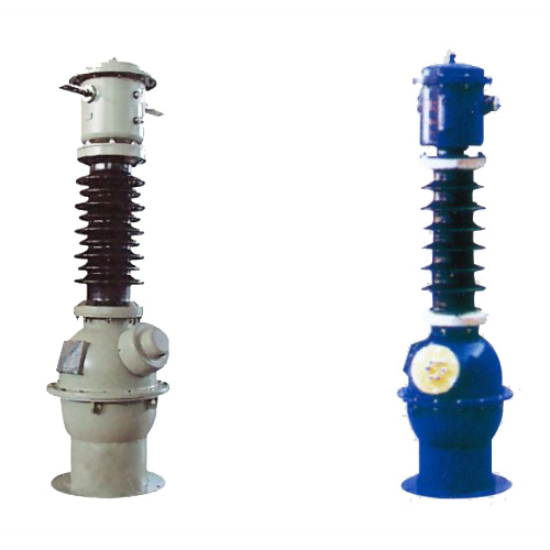
The CT-35K is a medium-voltage cast-resin current transformer engineered for reliable operation in 33kV (IEC) / 35kV (domestic) power systems. Designed in strict compliance with IEC 61869-2 and GB/T 20840.2, this instrument transformer serves dual roles in both revenue-grade metering and high-integrity protection schemes. Its robust construction leverages vacuum pressure impregnation (VPI) epoxy resin technology to encapsulate a grain-oriented electrical steel (GOES) core, ensuring long-term dielectric stability and mechanical resilience under harsh environmental conditions.
Operating Principle of Cast-Resin Insulation
Cast-resin insulation in the CT-35K employs a thermosetting epoxy system processed under vacuum and pressure to eliminate air voids and moisture ingress. This VPI technique results in a homogeneous, non-hygroscopic solid dielectric that maintains consistent insulation properties across temperature cycles from -40°C to +40°C. Unlike oil-filled alternatives, the solid resin matrix prevents leakage, eliminates fire hazards, and provides superior tracking resistance—critical for outdoor installations exposed to pollution, salt fog, or industrial contaminants. The resin’s coefficient of thermal expansion closely matches that of embedded copper windings and GOES laminations, minimizing internal stress during thermal transients and extending service life beyond 25 years.
Advantages Over Oil-Immersed Designs
Compared to traditional oil-immersed current transformers, the CT-35K offers significant operational and safety benefits. The absence of liquid dielectric eliminates risks of oil leakage, environmental contamination, and flammability—making it ideal for indoor substations, urban networks, and environmentally sensitive zones. Maintenance requirements are drastically reduced; no oil sampling, level checks, or gas monitoring is needed. Additionally, the compact footprint and lighter weight simplify handling and mounting on busbars or switchgear panels. Electromagnetic performance remains stable over time due to the hermetic seal provided by the resin, which prevents oxidation of the magnetic core and degradation of winding insulation—key factors in maintaining accuracy class integrity throughout the transformer’s lifecycle.
Typical Applications Overview
The CT-35K is deployed across diverse infrastructure segments requiring precise current measurement and fault discrimination. Primary use cases include utility-owned transmission substations operating at 33kV nominal voltage, industrial facilities with self-generation or cogeneration units interfacing at 35kV, and renewable energy plants (solar farms, wind parks) connecting to medium-voltage grids. Its dual-winding configuration—typically one for 0.2S/0.5 metering and another for 5P20 protection—enables simultaneous compliance with billing accuracy mandates and relay coordination requirements. The unit is suitable for both indoor GIS and outdoor AIS installations, with optional creepage extension sheds for coastal or high-pollution environments per IEC 60815.
Technical Specifications
The CT-35K is engineered to meet stringent electrical and environmental demands of modern power systems. Below is a comprehensive specification table followed by detailed service condition parameters.
| Parameter | Value |
|---|---|
| Rated System Voltage (IEC) | 33 kV |
| Domestic System Voltage | 35 kV |
| Insulation Level (LI/AC) | 170 kV / 70 kV |
| Primary Current Ratings | 50 A to 3150 A (standard); up to 4000 A (custom) |
| Secondary Current | 1 A or 5 A |
| Accuracy Classes | Metering: 0.2S, 0.5; Protection: 5P10, 5P20, 10P20 |
| Rated Burden (per class) | 5 VA to 30 VA (adjustable based on application) |
| Short-Time Thermal Current | 25 kA for 1 s (Ith) |
| Dynamic Withstand Current | 63 kA peak (Idyn) |
| Core Material | Grain-Oriented Electrical Steel (GOES), CRGO grade |
| Insulation System | VPI Epoxy Resin, UL 94 V-0 rated |
| Ambient Temperature Range | -40°C to +40°C |
| Maximum Altitude | 1000 m above sea level (derating required >1000 m) |
| Relative Humidity | Up to 95% non-condensing |
Standard Service Conditions
The CT-35K is rated for standard service conditions as defined in IEC 61869-2 Clause 5. Ambient temperature must not exceed +40°C (24-hour average ≤ +35°C), with a minimum of -40°C for cold-climate variants. Relative humidity may reach 95% provided condensation does not occur on external surfaces—a condition mitigated by the hydrophobic nature of the epoxy resin. Installation altitude is limited to 1000 m; for sites between 1000–2000 m, the power frequency withstand voltage must be reduced by 1% per 100 m increment above 1000 m. The transformer assumes symmetrical three-phase operation with total harmonic distortion (THD) ≤ 5% under normal load. Transient overvoltages must remain within the specified LI/AC insulation levels (170/70 kV).
Electrical Performance Parameters
Key electrical characteristics include a composite error ≤ ±0.2% at 100% rated current for 0.2S class windings, ensuring compliance with ISO/IEC 17025 for revenue metering. Protection windings exhibit a limiting factor (ALF) of 20 at 5P20 rating, meaning the transformer maintains ≤5% composite error up to 20× rated current during fault conditions. Burden tolerance is ±10% of declared value; exceeding this may shift accuracy class or cause saturation during high-magnitude faults. The magnetizing current at 10% of rated secondary voltage must not exceed 0.5 mA for metering cores, verified during factory testing per IEC 61869-2 Annex B.
Typical Applications
The CT-35K’s dual functionality enables deployment across critical infrastructure sectors where measurement fidelity and protection reliability are non-negotiable.
Substation Secondary Metering
In utility-owned 33kV/35kV substations, the CT-35K supplies accurate current signals to revenue meters compliant with EN 50470 or ANSI C12.20 standards. The 0.2S class winding ensures billing accuracy even at 1% of rated current—essential for detecting low-load theft or verifying distributed generation export. For example, a 600/5A CT-35K with 0.2S/5 VA burden connected to a Class 0.2 meter achieves ±0.3% total system error, well within regulatory limits. The cast-resin housing resists UV degradation and thermal cycling, maintaining calibration stability over decades without recalibration.
Industrial Power Distribution
Large manufacturing plants often operate internal 35kV distribution networks fed from dedicated grid connections. Here, the CT-35K monitors main incomers and large motor feeders (e.g., 2 MW+ induction motors). The 5P20 protection winding interfaces with numerical relays (e.g., SEL-351, Siemens 7SJ62) to provide instantaneous overcurrent and earth-fault tripping. During a phase-to-phase fault drawing 12 kA, the CT delivers a linear secondary signal up to 20× primary rating (e.g., 12,000 A on a 600 A unit), enabling precise time-current coordination with downstream devices.
Renewable Energy Integration
Solar photovoltaic farms and onshore wind parks frequently connect to the grid via 33kV collection systems. The CT-35K measures active/reactive power export for settlement and detects islanding conditions through vector shift relays. Its low remanence GOES core minimizes residual flux after fault clearance—critical for rapid re-synchronization post-trip. In a 50 MW solar plant, multiple CT-35K units on combiner transformers feed data to SCADA systems, supporting real-time performance ratio (PR) calculations and curtailment compliance.
Rural and Suburban Distribution Networks
For utilities modernizing aging infrastructure, the CT-35K replaces legacy oil-filled units in pole-mounted or pad-mounted switchgear serving suburban neighborhoods. Its maintenance-free design reduces outage durations during upgrades. In rural microgrids with diesel hybridization, the CT enables precise fuel consumption tracking by correlating generator output with load profiles. The standard 300/1A ratio with 0.5/5P10 windings balances metering needs against cost-sensitive protection requirements typical in these applications.
Compliance with International Standards
The CT-35K is certified to both global and domestic standards, ensuring interoperability and regulatory acceptance worldwide.
IEC 61869-2 Compliance Details
IEC 61869-2 governs the performance, testing, and marking of instrument transformers for AC systems. The CT-35K meets all mandatory clauses, including insulation coordination (Clause 6), temperature rise limits (≤60 K for resin, per Clause 7), and short-circuit withstand (Clause 8). Factory tests include power frequency withstand (70 kV rms for 1 min), partial discharge (<10 pC at 1.2 × Um/√3), and accuracy verification across 1–120% of rated current. Type tests—conducted every five years or after design changes—validate dynamic withstand (63 kA peak) and thermal endurance (25 kA/1s). All units bear permanent markings per Clause 10: model, ratio, accuracy classes, burden, and standard reference.
GB/T 20840.2 Alignment
For Chinese markets, the CT-35K complies with GB/T 20840.2, which largely harmonizes with IEC 61869-2 but includes localized requirements. Key differences include stricter partial discharge limits (<5 pC at 1.2 × Um/√3) and mandatory seismic testing for regions in Zone II or higher per GB 50260. The domestic standard also specifies unique terminal labeling (e.g., “J” for metering, “B” for protection) and requires type test reports issued by CNAS-accredited labs. Despite these nuances, the core design remains identical, allowing global inventory consolidation.
Testing and Certification Requirements
Certification involves third-party validation by bodies such as KEMA, CESI, or China Electric Power Research Institute (CEPRI). Routine tests (100% production) cover ratio, polarity, insulation resistance (>1000 MΩ at 2500 V DC), and winding continuity. Sample tests (per batch) include temperature rise and accuracy mapping. Type tests—valid for five years—encompass impulse voltage (170 kV peak), short-circuit force withstand, and environmental conditioning (thermal shock, humidity). Certificates explicitly reference both IEC 61869-2:2012 and GB/T 20840.2-2014 editions, facilitating customs clearance and grid interconnection approvals.
On-Site Testing Procedures
Post-installation verification ensures the CT-35K performs as specified under field conditions.
Insulation Resistance Test
Using a 2500 V DC megohmmeter, measure insulation resistance between primary-to-secondary, primary-to-ground, and secondary-to-ground. Acceptance criterion: ≥1000 MΩ at 20°C. Correct for temperature using RT2 = RT1 × 2(T1-T2)/10. Low readings indicate moisture ingress or resin cracking—requiring drying or replacement. Perform before and after high-voltage tests to detect insulation damage.
Turns Ratio Test
Apply a low-voltage AC source (e.g., 120 V) to the primary and measure secondary voltage. Calculate actual ratio: Nactual = Vp/Vs. Tolerance: ±0.2% for metering windings, ±0.5% for protection. Example: 600/5A CT should yield 120:1 ratio; measured 119.8:1 is acceptable. Use a precision ratio bridge (e.g., Omicron CT Analyzer) for automated verification.
Polarity Test
Verify reducing polarity per IEC 61869-2 Figure 3. Connect a 1.5 V battery momentarily across P1–P2; observe secondary voltage spike direction with an oscilloscope or analog voltmeter. Positive deflection at S1 confirms correct polarity. Incorrect polarity causes 180° phase shift—disastrous for differential or directional protection schemes.
Power Frequency Withstand Voltage Test
Apply 70 kV rms (50/60 Hz) between primary and grounded secondary/enclosure for 1 minute. Monitor for flashover, excessive leakage current (>1 mA), or audible discharge. Pre-test: ensure ambient humidity <80%. Post-test: repeat insulation resistance to confirm integrity. This validates dielectric strength after transport-induced microcracks.
Short-Circuit Test (for CT)
Inject 10–20× rated secondary current (e.g., 100 A into 5 A winding) and verify linearity via oscilloscope or CT analyzer. Saturation should not occur below ALF (e.g., 20× for 5P20). Composite error must remain within class limits. This simulates fault conditions to confirm protection winding performance.
Preventive Maintenance Guide
Although cast-resin CTs require minimal upkeep, scheduled inspections prevent latent failures.
Periodic Inspection Protocol
Conduct annual visual and electrical checks: inspect for surface tracking, cracks, or discoloration; clean with isopropyl alcohol if contaminated; verify terminal tightness (torque: 15 N·m for M10 studs); and re-measure insulation resistance. In coastal areas, check for salt deposits on sheds—remove with deionized water. Document trends: a 20% drop in insulation resistance over two years warrants diagnostic testing.
Maintenance Intervals and Fault Diagnosis
Every five years, perform full electrical characterization: ratio, polarity, excitation curve, and burden verification. Common faults include open secondary circuits (causing dangerous overvoltages), core saturation from incorrect burden, and thermal degradation from loose connections. Symptoms: overheating (>70°C surface temp), abnormal hum, or metering drift. Replace if partial discharge exceeds 20 pC during on-site PD testing. Below is a recommended schedule:
| Interval | Action |
|---|---|
| Annually | Visual inspection, IR scan, insulation resistance |
| Every 5 Years | Full electrical tests, excitation curve, burden check |
| After Major Fault | Ratio, polarity, insulation withstand verification |
Conclusion
The CT-35K 33kV cast-resin current transformer represents a benchmark in medium-voltage instrumentation, combining IEC 61869-2 and GB/T 20840.2 compliance with field-proven reliability. Its VPI epoxy resin encapsulation eliminates the operational liabilities of oil-filled designs while delivering metrological precision for revenue metering (0.2S class) and robust fault response for protection (5P20). Engineered with GOES cores and optimized magnetic circuits, the unit maintains accuracy across wide load ranges—from light residential demand to industrial fault currents—without recalibration. The standardized 170/70 kV insulation level ensures compatibility with global 33kV networks, while its compact, maintenance-free profile reduces lifecycle costs in both urban substations and remote renewable sites. With a design life exceeding 25–30 years under standard service conditions, the CT-35K provides a future-proof solution for utilities and industrial operators prioritizing grid resilience, regulatory compliance, and operational efficiency. Its dual-certification framework further streamlines procurement for multinational projects, eliminating the need for region-specific variants without compromising performance or safety margins.