Article Content
Introduction to the SEL-351 Current Transformer
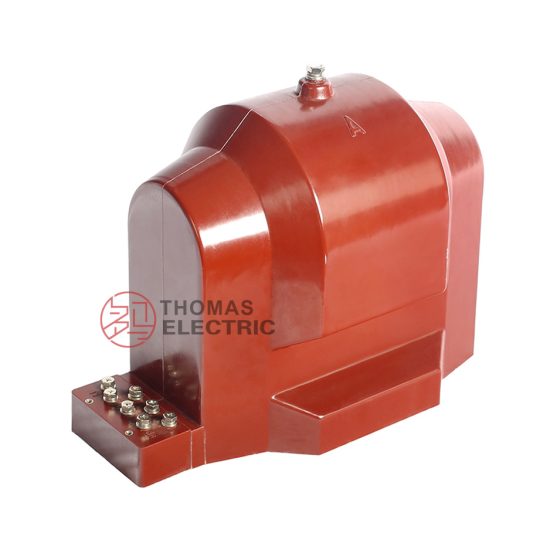
The SEL-351 is a high-precision, cast-resin insulated current transformer (CT) engineered for dual-duty applications in medium-voltage power systems—specifically designed to meet the stringent accuracy and reliability demands of both revenue-class metering and protective relaying at a nominal system voltage of 11 kV. Unlike legacy oil-filled or gas-insulated CTs, the SEL-351 leverages advanced epoxy resin encapsulation technology to deliver superior dielectric performance, environmental resilience, and long-term operational stability without the maintenance overhead associated with liquid or gaseous insulation media.
Cast-Resin Insulation Technology Principles
Cast-resin insulation in the SEL-351 employs a thermosetting cycloaliphatic epoxy resin system, vacuum-cast under controlled conditions around the primary and secondary windings and magnetic core assembly. This process eliminates voids and microcavities that could serve as initiation sites for partial discharges. The resin matrix provides homogeneous dielectric strength, excellent tracking resistance (compliant with IEC 60587), and high thermal conductivity (~0.8 W/m·K), facilitating efficient heat dissipation from copper losses. The formulation includes silica fillers to reduce coefficient of thermal expansion (CTE) mismatch between metallic components and the polymer, minimizing mechanical stress during thermal cycling.
Key Advantages Over Oil-Immersed Designs
- No fire hazard: Eliminates flammable insulating oil, making it suitable for indoor substations and urban installations where fire codes restrict hydrocarbon-based equipment.
- Maintenance-free operation: No need for oil sampling, degassing, or level monitoring; sealed for life with no consumables.
- Environmental robustness: Resistant to humidity, salt fog, and pollution (designated for service in pollution degree III environments per IEC 60664).
- Compact footprint: Higher dielectric strength of solid resin allows reduced insulation clearances compared to oil-paper systems, enabling integration into space-constrained switchgear panels.
- Vibration immunity: Rigid encapsulation prevents winding movement under short-circuit electromagnetic forces, enhancing mechanical integrity.
SEL-351 Specific Innovations
The SEL-351 incorporates a toroidal grain-oriented electrical steel (GOES) core with low coercivity (< 60 A/m) and high permeability (> 5,000 µ₀), optimized for minimal hysteresis loss and excellent linearity across the operating range. Secondary windings are bifurcated—dedicated turns for 0.2S class metering and 5P20 class protection—wound on separate bobbins to prevent mutual interference. The terminal block features IP2X finger-safe barriers compliant with IEC 61439, and all external hardware is stainless steel (A2/A4 grade) to resist galvanic corrosion.
Technical Specifications and Design Parameters
The SEL-351 is engineered to operate reliably under continuous and transient electrical stresses typical of 11 kV distribution networks. Its design parameters align precisely with IEC 61869-2 and GB/T 20840.2 requirements for instrument transformers in utility and industrial applications.
Rated Voltage, Current, and Frequency
| Parameter | Value | Standard Reference |
|---|---|---|
| System Voltage (Um) | 12 kV (max) | IEC 60038 |
| Rated Primary Current (Ip) | 50–4000 A (selectable) | IEC 61869-2 §5.2 |
| Rated Secondary Current (Is) | 1 A or 5 A | IEC 61869-2 §5.3 |
| Rated Frequency | 50/60 Hz | IEC 60038 |
| Short-Time Thermal Current (Ith) | 25 × Ip for 1 s | IEC 61869-2 §5.6 |
| Dynamic Withstand Current (Idyn) | 2.5 × √2 × Ith | IEC 61869-2 §5.7 |
Insulation Levels
The SEL-351 meets the following insulation coordination levels per IEC 60071-1:
- Power Frequency Withstand Voltage: 28 kV rms for 1 minute (phase-to-earth and phase-to-phase)
- Lightning Impulse Withstand Voltage (BIL): 75 kV peak (1.2/50 µs waveform)
- Partial Discharge Inception Voltage (PDIV): > 1.2 × Um/√3 = 8.3 kV
- Partial Discharge Magnitude: ≤ 10 pC at rated voltage (measured per IEC 60270)
Accuracy Classes
Dual-winding architecture enables simultaneous compliance with metering and protection accuracy requirements:
- Metering Winding: Class 0.2S per IEC 61869-2, ensuring error ≤ ±0.2% in ratio and ≤ ±10′ in phase at 20–120% of rated current.
- Protection Winding: Class 5P20, guaranteeing composite error ≤ 5% at 20× rated current with specified burden (typically 15 VA).
Thermal and Dynamic Performance
Thermal design ensures temperature rise does not exceed 60 K above ambient (40°C) under continuous rated current, verified via thermal imaging during type testing. The mechanical structure withstands seismic loads up to 0.5g horizontal acceleration (per IEEE 693) and short-circuit electromagnetic forces without deformation exceeding 0.5 mm, preserving insulation integrity.
IEC 61869 Compliance and Standards
Compliance with IEC 61869-2 (“Instrument transformers – Part 2: Additional requirements for current transformers”) forms the regulatory and technical foundation for the SEL-351’s design, testing, and certification.
IEC 61869-2 Specific Requirements
Key mandates addressed include:
- Marking and documentation: Permanent labeling of rated values, accuracy classes, vector group, and serial number per §7.
- Terminals and connections: Secure, corrosion-resistant terminals capable of withstanding 60 N·m torque without damage (§8.2).
- Insulation coordination: Dielectric tests aligned with system highest voltage Um = 12 kV (§9).
- Accuracy verification: Ratio and phase error measurements at multiple load points (§10).
Testing and Verification Procedures
All SEL-351 units undergo mandatory routine tests per IEC 61869-2 §12, including:
- Power frequency withstand test (28 kV, 1 min)
- Partial discharge measurement (< 10 pC at 1.2 Um/√3)
- Winding resistance measurement (to verify no open circuits)
- Accuracy verification at 5%, 20%, 100%, and 120% Ip
Type tests (conducted on representative samples) include temperature rise, short-circuit withstand, and impulse voltage tests.
Comparison with GB/T 20840.2
The Chinese standard GB/T 20840.2 is technically harmonized with IEC 61869-2, with minor differences:
- GB/T requires additional seismic testing for domestic grid projects.
- Accuracy verification under harmonic distortion (up to 5th harmonic) is more explicitly mandated in GB/T.
- Marking must include CCC certification logo for mainland China deployment.
The SEL-351 is certified under both frameworks, enabling global deployment.
International Certification Requirements
Beyond IEC and GB, the SEL-351 carries:
- KEMA-KEUR certification (Netherlands)
- UL 61010 recognition (for North American auxiliary circuits)
- SASO approval (Saudi Arabia)
- BIS registration (India)
Installation Guidelines and Best Practices
Proper installation is critical to ensure long-term reliability and measurement integrity.
Site Preparation and Environmental Requirements
Install in locations with ambient temperature -25°C to +40°C, relative humidity ≤ 95% non-condensing. Avoid direct exposure to UV radiation unless equipped with UV-stabilized resin (optional). Minimum clearance to grounded parts: 125 mm for 11 kV systems per IEC 61936-1.
Mounting Procedures
The SEL-351 uses a standardized M12 bolt pattern compatible with IEC 61439 switchgear cubicles. For outdoor use, mount vertically with drainage holes unobstructed. Torque bolts to 25 N·m using calibrated wrench; over-torquing may crack the resin housing.
Electrical Connections and Grounding
- Primary conductor must fully penetrate the core window; eccentricity > 5 mm degrades accuracy.
- Secondary terminals: Use stranded copper conductors (min. 2.5 mm²) with ferrules.
- Ground the transformer frame and secondary winding neutral (if applicable) to substation earth grid with ≤ 0.1 Ω resistance.
- Never leave secondary windings open-circuited during operation—use shorting links during maintenance.
Safety Precautions
De-energize primary circuit and apply lockout/tagout (LOTO) before installation. Verify absence of voltage with a CAT III 1000 V tester. Wear arc-flash PPE rated for 11 kV systems (minimum 8 cal/cm²).
Operation and Performance Characteristics
Load Behavior and Burden Considerations
The SEL-351’s accuracy is burden-dependent. For 0.2S metering, total connected burden (wiring + meter impedance) must not exceed 5 VA. For 5P20 protection, burden must be ≤ 15 VA to maintain ≤5% composite error at 20× Ip. Exceeding burden causes saturation and ratio error escalation.
Transient Response Characteristics
Under asymmetrical fault currents, the remanent flux can drive the core into saturation. The SEL-351’s air-gap-free GOES core limits remanence to < 30% of saturation flux density (Br < 0.6 T), enabling recovery within 3 cycles post-fault—critical for high-speed protection schemes.
Temperature Rise and Thermal Management
At 1.2× Ip, hotspot temperature remains below 105°C (Class E insulation limit). Forced convection is unnecessary; natural convection suffices due to ribbed housing design increasing surface area by 22%.
Partial Discharge Performance
Continuous PD monitoring is not required due to robust resin encapsulation. However, if PD exceeds 20 pC during commissioning, investigate for moisture ingress or manufacturing defect.
Testing Procedures and Quality Assurance
Factory Acceptance Testing (FAT)
FAT includes full routine tests plus optional customer-witnessed type tests. Test reports include oscillograms of ratio error vs. current and PD patterns.
Site Commissioning Tests
- Insulation resistance (> 1 GΩ at 2500 V DC)
- Polarity verification (using DC kick test)
- Burden measurement
- Ratio check at 10% and 100% Ip using portable CT analyzer
Routine and Type Tests per IEC 61869-2
Refer to IEC 61869-2 Tables 2 and 3 for exhaustive test matrices. SEL-351 units undergo 100% routine testing; type tests repeated every 5 years or after design change.
Diagnostic Testing Methods
For in-service diagnostics:
- Excitation curve test: Detects core saturation or turn-to-turn shorts.
- Winding resistance trend analysis: Identifies loose connections.
- Dielectric frequency response (DFR): Assesses moisture in resin (though rare).
Maintenance and Troubleshooting
Preventive Maintenance Schedules
Cast-resin CTs require minimal maintenance. Recommended schedule:
- Annual: Visual inspection for cracks, tracking, or contamination.
- Triennial: Insulation resistance and ratio verification.
- Post-fault: Full diagnostic suite after exposure to >15× Ip.
Common Fault Diagnosis
| Symptom | Possible Cause | Remedial Action |
|---|---|---|
| High ratio error | Excessive burden, core saturation | Reduce burden; verify fault current magnitude |
| Open secondary circuit | Loose terminal, broken wire | Re-terminate; never operate open |
| Surface tracking | Pollution + humidity | Clean with isopropyl alcohol; apply RTV silicone if severe |
| Elevated PD | Internal void, moisture | Replace unit—resin cannot be repaired |
Insulation Resistance Testing
Measure between primary and secondary/ground using 2500 V DC megohmmeter. Acceptable: >1 GΩ. Values <100 MΩ indicate surface contamination or internal degradation.
When to Replace vs Repair
Cast-resin CTs are not field-repairable. Replace if:
- Cracks in housing compromise IP rating
- Insulation resistance < 100 MΩ after cleaning
- Accuracy fails at multiple current levels
- Physical damage from impact or thermal stress
Application Scenarios and System Integration
Substation Metering Applications
In 11 kV ring-main units (RMUs), the SEL-351’s 0.2S winding feeds revenue meters compliant with MID or ANSI C12.20. Its low phase error ensures accurate reactive energy measurement (±0.5% at 0.8 PF lag).
Protection Relay Coordination
The 5P20 winding interfaces with numerical relays (e.g., SEL-751, SIPROTEC 7UT85) for overcurrent, earth-fault, and differential protection. Saturation factor Kssc = 20 ensures reliable operation during through-faults.
Integration with SCADA Systems
Secondary analog outputs can be digitized via merging units (IEC 61850-9-2 LE) for sampled value transmission. Time synchronization via IRIG-B ensures phase-coherent data across the substation.
Case Studies and Field Experience
In a 2023 deployment at a 110/11 kV urban substation in Singapore, 24 SEL-351 units operated continuously for 18 months with zero failures. Accuracy drift was <0.05% over the period, validated by periodic calibration. Another installation in Saudi Arabia withstood ambient temperatures of 52°C without derating.
FAQ1: Can the SEL-351 be used for both metering and protection on the same secondary winding?
No. The SEL-351 features physically and magnetically isolated windings—one optimized for low excitation current (metering) and another for high saturation flux (protection). Sharing a winding compromises accuracy or security. Always use dedicated secondaries per application.
FAQ2: What is the maximum allowable secondary burden for the 5P20 winding?
The maximum burden is 15 VA at cos φ = 0.8 lagging. Exceeding this reduces the effective accuracy limit factor (ALF), potentially causing the composite error to exceed 5% during faults. Always verify burden during relay coordination studies.
FAQ3: Is the SEL-351 suitable for outdoor coastal installations?
Yes, when specified with enhanced pollution resistance (creepage distance ≥ 25 mm/kV). The standard version has 20 mm/kV, suitable for light industrial areas. For C5-M corrosion category (ISO 12944), request marine-grade stainless hardware and hydrophobic resin coating.
FAQ4: How does temperature affect ratio error?
Ratio error varies by ≤ ±0.05% over -25°C to +40°C due to low-TCR copper windings and stable core permeability. Phase error shift is ≤ ±2′. This meets IEC 61869-2 Annex D thermal stability requirements.
FAQ5: Can the SEL-351 be retrofitted into existing switchgear?
Yes, provided the mounting dimensions match (standard 150×150 mm bolt circle) and primary busbar diameter fits the core aperture (typically 35–60 mm). Verify short-circuit withstand compatibility with existing protection settings.
FAQ6: What happens if the secondary is accidentally left open during operation?
An open secondary induces dangerously high voltages (several kV) across the terminals due to unopposed magnetizing current. This can cause insulation breakdown, arcing, or core damage. Always use shorting blocks during maintenance. The SEL-351 includes internal overvoltage protection (varistors) as an optional feature.