Article Content
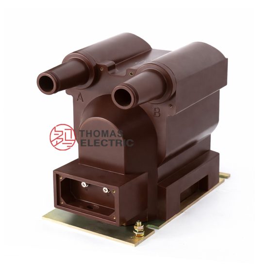
Introduction to the ZW-10 Current Transformer
The ZW-10 is a high-reliability, indoor-type cast-resin insulated current transformer (CT) engineered for critical metering and protection functions in 11 kV medium-voltage (MV) power distribution systems. Designed in strict compliance with IEC 61869-2 and GB/T 20840.2, this device exemplifies modern advancements in solid dielectric insulation technology for instrument transformers.
Cast-Resin Insulation Technology Principles
Cast-resin insulation in the ZW-10 employs a thermosetting epoxy resin system—typically a cycloaliphatic or bisphenol-A-based formulation—vacuum-cast under controlled conditions around the primary conductor and secondary windings. This process eliminates air voids and moisture ingress pathways, resulting in a monolithic, void-free dielectric structure with high mechanical strength and excellent tracking resistance. The resin matrix encapsulates grain-oriented electrical steel (GOES) cores and copper windings, providing both electrical insulation and mechanical support.
Key material properties include:
- Relative permittivity (εr): 3.5–4.2 at 50 Hz
- Volume resistivity: >1014 Ω·cm
- Dielectric strength: ≥20 kV/mm
- Comparative Tracking Index (CTI): ≥600 V (IEC 60112)
Key Advantages Over Oil-Immersed Designs
Compared to traditional oil-filled CTs, the ZW-10’s cast-resin construction offers significant operational and safety benefits:
- Fire safety: Non-flammable, eliminating fire hazards in confined indoor switchgear rooms per IEC 61641.
- Maintenance-free operation: No oil sampling, degassing, or leakage monitoring required.
- Environmental resilience: Immune to oil oxidation, moisture absorption, and thermal cycling-induced seal degradation.
- Compact footprint: Higher dielectric strength allows reduced creepage and clearance distances, optimizing space in metal-enclosed switchgear.
- Vibration resistance: Rigid encapsulation minimizes core movement under short-circuit forces, preserving accuracy.
ZW-10 Specific Innovations
The ZW-10 incorporates several design enhancements tailored for MV substation reliability:
- Dual-core configuration (optional): One core optimized for 0.2S/0.5S metering accuracy, another for 5P10/5P20 protection class.
- Integrated electrostatic shields between primary and secondary windings to suppress capacitive coupling and improve transient response.
- Precision-wound secondary coils with low inter-turn capacitance to minimize phase angle error under burden variations.
- UV-stabilized outdoor-rated resin variants available for pole-mounted applications.
Technical Specifications and Design Parameters
The ZW-10 is engineered to meet stringent performance criteria across electrical, thermal, and mechanical domains.
Rated Voltage, Current, and Frequency
| Parameter | Value | Standard Reference |
|---|---|---|
| System Voltage (Um) | 12 kV (rated for 11 kV systems) | IEC 60038 |
| Primary Rated Current (Ip) | 50 A to 3150 A (standard steps) | IEC 61869-2 Table 1 |
| Secondary Rated Current (Is) | 1 A or 5 A | IEC 61869-2 |
| Rated Frequency | 50 Hz or 60 Hz | IEC 60044-1 |
Insulation Levels
The ZW-10 complies with IEC 60071-1 insulation coordination requirements for 12 kV systems:
- Power Frequency Withstand Voltage: 28 kV rms, 1 min (phase-to-earth)
- Lightning Impulse Withstand Voltage (BIL): 75 kV peak (1.2/50 μs waveform)
- Partial Discharge Inception Voltage (PDIV): ≥1.2 × Um/√3 = 8.3 kV
- Maximum Partial Discharge Magnitude: ≤10 pC at 1.2 × Um/√3
Accuracy Classes
Dual-core models support independent accuracy specifications:
| Application | Accuracy Class | Max Composite Error | Burden (VA) |
|---|---|---|---|
| Metering | 0.2S / 0.5S | ±0.2% / ±0.5% | 5–15 VA |
| Protection | 5P10 / 5P20 | ≤5% at 10×/20× Ipn | 15–30 VA |
Note: The “S” suffix denotes special accuracy requirements for wide-range metering (e.g., smart grid revenue metering per IEC 62053-22).
Thermal and Dynamic Performance
- Short-Time Thermal Current (Ith): 20–40 kA for 1 s (depends on primary rating)
- Dynamic Withstand Current (Idyn): 2.5 × Ith (peak)
- Temperature Rise Limit: ≤60 K for windings (measured by resistance method per IEC 61869-2)
- Ambient Operating Range: –25°C to +40°C (indoor); –40°C to +45°C (outdoor variant)
IEC 61869 Compliance and Standards
IEC 61869-2 Specific Requirements
IEC 61869-2:2012 (“Instrument transformers – Part 2: Additional requirements for current transformers”) defines essential performance, testing, and marking criteria. The ZW-10 satisfies all mandatory clauses, including:
- Clause 5.3: Insulation coordination per IEC 60071
- Clause 5.5: Accuracy verification under defined burden and frequency
- Clause 5.7: Temperature rise limits under rated continuous current
- Clause 5.9: Short-circuit withstand capability
- Clause 6.4: Partial discharge measurement methodology
Testing and Verification Procedures
Compliance is demonstrated through a comprehensive test matrix:
- Type Tests: Performed once per design (e.g., temperature rise, short-circuit, PD)
- Routine Tests: Conducted on every unit (e.g., power frequency withstand, accuracy check, polarity verification)
- Special Tests: On request (e.g., seismic withstand, chopped impulse)
Comparison with GB/T 20840 Standards
GB/T 20840.2—China’s national adoption of IEC 61869-2—is technically harmonized but includes localized requirements:
- Stricter partial discharge limits in some utility specifications (e.g., ≤5 pC at 1.2 Um/√3)
- Mandatory seismic qualification for regions in Zone 8+ per GB 50260
- Additional creepage distance requirements for coastal/polluted environments (≥20 mm/kV)
The ZW-10 is dual-certified, bearing both IEC 61869-2 and GB/T 20840.2 marks, facilitating global deployment.
International Certification Requirements
Beyond base standards, the ZW-10 often undergoes third-party certification:
- KEMA-KEUR (Netherlands)
- UL 61869 (USA/Canada)
- SASO (Saudi Arabia)
- BIS (India)
Installation Guidelines and Best Practices
Site Preparation and Environmental Requirements
Install only in clean, dry environments with relative humidity ≤80% (non-condensing). Avoid locations with:
- Chemical vapors (e.g., chlorine, sulfur compounds)
- Excessive dust or conductive particulates
- Mechanical vibration sources (>0.5 g)
Mounting Procedures (Indoor/Outdoor)
The ZW-10 features standardized M12 or M16 threaded studs for secure panel or busbar mounting. Key steps:
- Verify mechanical alignment to prevent stress on primary conductor.
- Torque mounting bolts to 45–60 N·m (per manufacturer spec).
- Ensure minimum clearance to grounded parts: ≥125 mm (11 kV system).
- For outdoor use, orient secondary terminal box downward to prevent water ingress.
Electrical Connections and Grounding
- Primary conductor must fully penetrate the central aperture without contact.
- Secondary terminals: Use ring lugs with anti-oxidant compound; torque to 2.5 N·m.
- Critical: Secondary winding must NEVER be left open-circuited during operation—use shorting links during maintenance.
- Ground the transformer frame and electrostatic shield via dedicated 6 mm² Cu conductor to substation earth grid.
Safety Precautions During Installation
Adhere to IEC 61936-1 and local arc-flash protocols:
- De-energize upstream circuit and apply lockout/tagout (LOTO).
- Perform dielectric tests only with calibrated, current-limited HV sources.
- Wear arc-rated PPE (Category 2 minimum for 11 kV).
Operation and Performance Characteristics
Load Behavior and Burden Considerations
The ZW-10’s accuracy is burden-dependent. Total connected burden (Zb) must not exceed rated VA:
- Metering circuits: Typically 2–10 VA (watt-hour meters, AMR devices)
- Protection circuits: 5–25 VA (relays, fault recorders)
Exceeding burden causes increased ratio and phase errors, potentially compromising relay coordination.
Transient Response Characteristics
Under fault conditions, the ZW-10 exhibits:
- Remanence factor (kr) ≤ 0.7 due to GOES core with controlled hysteresis
- Time to saturation > 30 ms at 20× Ipn (for 5P20 class)
- DC offset immunity up to 100% (X/R = 15)
Temperature Rise and Thermal Management
Continuous operation at 1.2× Ipn results in ≤60 K rise above ambient. Heat dissipates radially through the resin body—no forced cooling required. Avoid installing near heat sources (e.g., power cables, reactors).
Partial Discharge Performance
Factory-tested per IEC 60270, the ZW-10 maintains PD levels <10 pC at 1.2 Um/√3 throughout its 30-year service life, provided operating voltage does not exceed Um.
Testing Procedures and Quality Assurance
Factory Acceptance Testing (FAT)
Each unit undergoes:
- Winding resistance measurement
- Ratio and polarity verification
- Accuracy test at 5%, 20%, 100%, and 120% Ipn
- Power frequency withstand (28 kV, 1 min)
- Partial discharge scan (10–15 kV range)
Site Commissioning Tests
Post-installation verification includes:
- Insulation resistance (>1000 MΩ @ 2500 V DC)
- Secondary circuit continuity and burden check
- Polarity confirmation via DC kick test
- Ratio verification using portable CT analyzer
Routine and Type Tests per IEC 61869-2
Type tests (design validation):
- Temperature rise
- Short-time current
- Dynamic current
- Capacitance and tan δ (if applicable)
Diagnostic Testing Methods
For in-service assessment:
- Excitation (knee-point) test to detect core degradation
- Insulation resistance trend analysis
- Online PD monitoring (for critical feeders)
Maintenance and Troubleshooting
Preventive Maintenance Schedules
Cast-resin CTs require minimal maintenance:
- Visual inspection annually (cracks, discoloration, terminal corrosion)
- Insulation resistance test every 3–5 years
- Burden verification during relay calibration cycles
Common Fault Diagnosis
| Symptom | Possible Cause | Diagnostic Action |
|---|---|---|
| High ratio error | Open secondary, core saturation, burden overload | Check connections, measure burden, perform excitation test |
| Elevated temperature | Loose primary connection, excessive harmonic current | Thermal imaging, harmonic analysis |
| Cracking/resin discoloration | UV exposure (outdoor), thermal cycling fatigue | Replace if surface tracking observed |
Insulation Resistance Testing
Use a 2500 V megohmmeter:
- Primary-to-secondary/frame: >1000 MΩ
- Secondary-to-frame: >100 MΩ
A drop >50% from baseline indicates moisture ingress or resin degradation.
When to Replace vs Repair
Cast-resin CTs are not field-repairable. Replace if:
- Insulation resistance <100 MΩ
- Visible cracks or carbon tracking
- Accuracy fails after verifying external burden
Application Scenarios and System Integration
Substation Metering Applications
The ZW-10’s 0.2S class enables precise energy billing in:
- Utility revenue metering points
- Industrial plant sub-metering
- Demand-side management systems
Protection Relay Coordination
5P-class cores ensure reliable operation of:
- Overcurrent relays (IEC 60255-151)
- Differential protection schemes
- Earth-fault detection (residual CT configuration)
Coordination studies must account for CT saturation during high-magnitude faults.
Integration with SCADA Systems
Secondary outputs interface with:
- Numeric relays (e.g., SEL-751, Siemens 7SJ)
- RTUs and IEDs via analog inputs
- Power quality analyzers for harmonic monitoring
Case Studies and Field Experience
In a 2023 urban substation retrofit (Shanghai), 24 ZW-10 units replaced oil-filled CTs. Results after 18 months:
- Zero maintenance interventions
- Metering accuracy maintained within ±0.3%
- Successful tripping during 18 kA fault (5P20 verified)
FAQ1: Can the ZW-10 be used in 12 kV systems?
Yes. The ZW-10 is rated for Um = 12 kV, making it suitable for nominal 11 kV systems per IEC 60038. Continuous operation at 12 kV is permissible within thermal and dielectric limits.
FAQ2: What is the maximum allowable burden for a 5P20 class?
The rated burden for 5P20 is typically 15–30 VA. However, the actual maximum depends on the specific model’s knee-point voltage (Ek). Verify using: Zb(max) = Ek / (20 × Isn) – Rct, where Rct is secondary winding resistance.
FAQ3: Is outdoor installation possible?
Yes, with the outdoor-rated variant featuring UV-stabilized resin, hydrophobic surface treatment, and IP54 terminal box. Standard indoor models are not rated for direct weather exposure.
FAQ4: How does remanence affect protection performance?
Remanence (residual flux) can reduce the effective knee-point voltage, causing premature saturation during subsequent faults. The ZW-10’s GOES core and controlled air gaps (if present) limit kr ≤ 0.7, ensuring 5P20 performance even with DC offset.
FAQ5: Can multiple secondaries share one core?
No. Each accuracy class (metering, protection) requires a dedicated magnetic core to prevent cross-coupling and ensure independent performance. The ZW-10 uses physically separated cores within one housing.
FAQ6: What is the expected service life?
Under normal operating conditions (≤40°C ambient, no overvoltage), the ZW-10 has a design life of ≥30 years. Accelerated aging occurs above 50°C ambient or with sustained overcurrent (>1.2 Ipn).